A barcode scanner's field of view determines the area its camera sees at a given distance. For an OEM scan engine, that area must contain the complete code, its quiet zone and the movement allowed by the enclosure. Focus and image sampling then determine whether that code is a useful candidate for reading.
You can estimate coverage before building a bracket. The calculations below use published XL-609-SSR and G53-AI specifications, plus a clearly defined QR-code example. The results describe nominal geometry, not a measured decoding range.
Use horizontal and vertical FOV for the scan area
Datasheets may quote horizontal, vertical and diagonal field of view. Use the horizontal angle to estimate scan width and the vertical angle to estimate scan height. A diagonal angle cannot be substituted for either one.
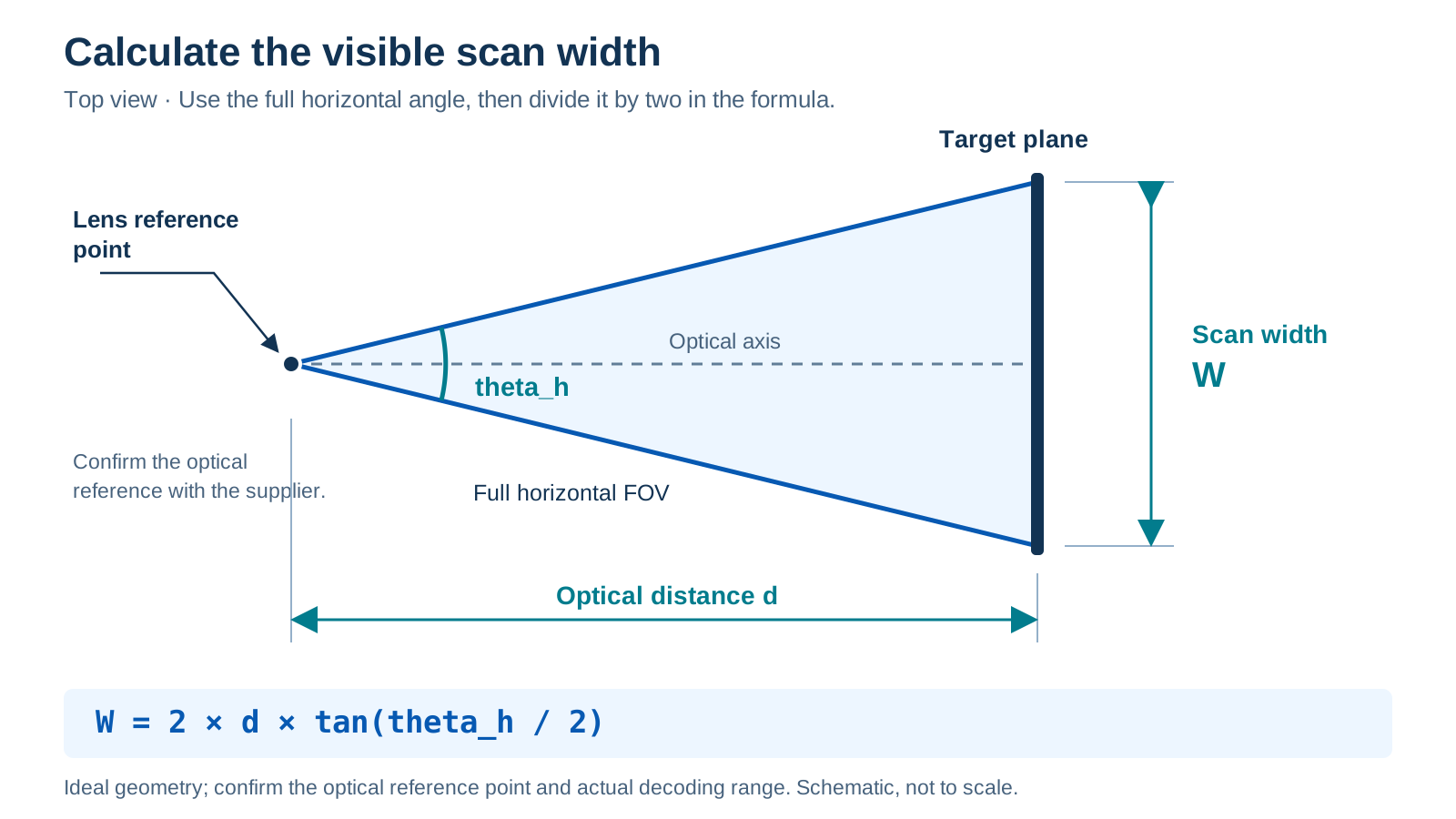
For an ideal, centered camera looking straight at a flat target:
Scan width W  = 2 * d * tan(horizontal FOV / 2)
Scan height H = 2 * d * tan(vertical FOV / 2)
Here, d is the optical distance to the target plane, measured from the reference point used by the optical model. The angles are full FOV angles; divide them by two inside the tangent. Use degree mode on a calculator, or convert degrees to radians in software.
The optical reference point can differ from the front of the housing. Ask the supplier to identify it before turning a rough calculation into a bracket dimension. These equations also assume a flat target perpendicular to the optical axis. Lens distortion, image cropping and a window can change the usable area. Edmund Optics explains the same geometry and its reference-point limitation in its field-of-view application note.
Worked example using two Xinlong scan engines
The English datasheets specify the following inputs:
| Model | Sensor image | Horizontal FOV | Vertical FOV | Nominal area at d = 100 mm |
|---|---|---|---|---|
| XL-609-SSR | 640 x 480 pixels | 67.4 degrees | 56 degrees | 133.4 x 106.3 mm |
| G53-AI | 1280 x 800 pixels | 48 degrees | 28 degrees | 89.0 x 49.9 mm |
For the XL-609-SSR, the width calculation is 2 * 100 * tan(67.4 / 2), giving approximately 133.4 mm. Its advertised 85.8-degree diagonal FOV is a separate specification.
The 100 mm distance is an arithmetic example. It does not establish that either engine reads a particular QR code there. Check the specified reading range for the same symbology and module size, then test the intended assembly. A Code 39 distance specification does not validate a QR-code distance.
At the same optical distance, the XL-609-SSR's wider nominal field covers more of the target plane. The G53-AI example places more horizontal sensor pixels across each millimeter. Neither result establishes an overall performance ranking: focus, code density, lighting and the decoding configuration still matter.
Use the current English source files when discussing the numbers: XL-609-SSR brochure and G53-AI specifications.
Geometry worksheet
Calculate your nominal scan area
Use full horizontal and vertical angles. The QR code is square, axis aligned and perpendicular to the optical axis. Standard QR quiet zones are fixed at four modules per side. This tool estimates geometry and sampling; it does not assess focus or predict decoding success.
- Nominal area, width x height
- QR module width
- Pixels per module, horizontal / vertical estimates
- Required envelope with placement tolerance
Include the QR quiet zone in the measured size
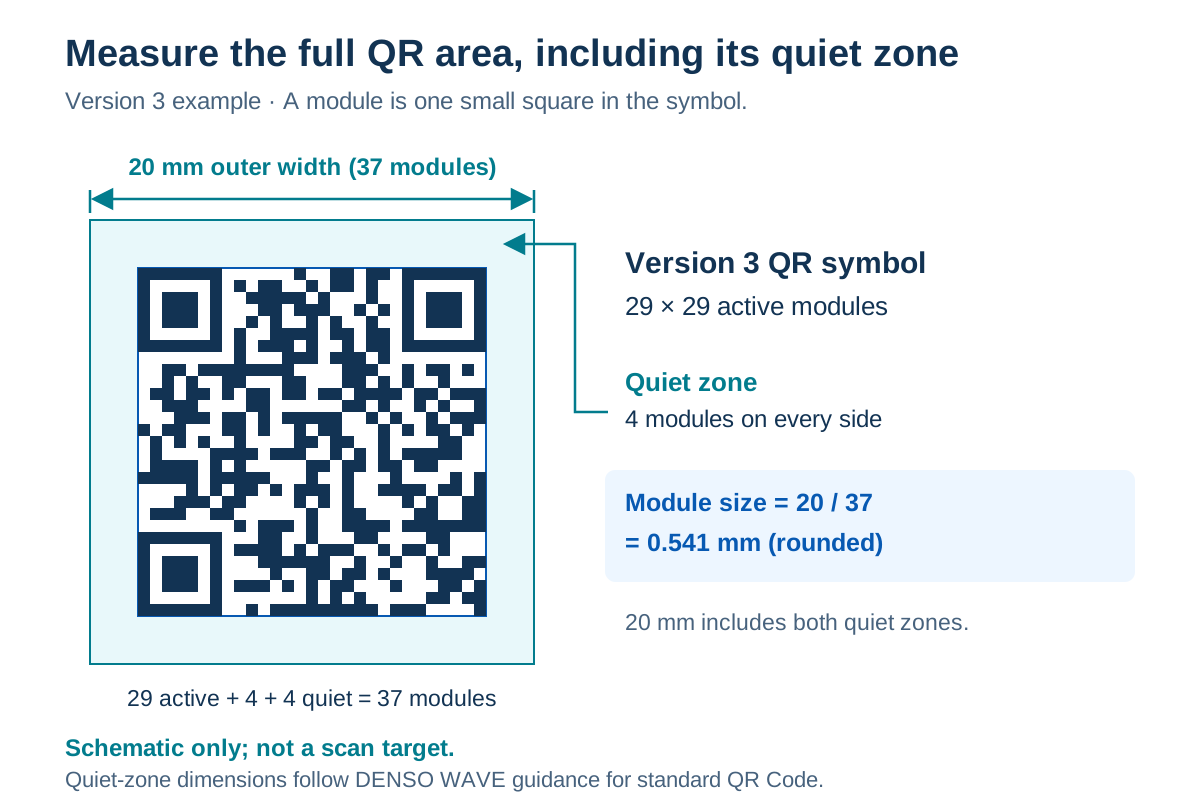
A standard QR Code needs a clear margin four modules wide on every side. A module is one small square in the code. DENSO WAVE's QR-code area guide explains the requirement and shows that Version 3 has 29 modules per side in the active symbol.
For that Version 3 symbol:
Active symbol:             29 modules per side
Quiet zone:                4 modules on each side
Total outer width:        37 modules
Example total print width: 20 mm, including the quiet zone
Module width:             20 / 37 = approximately 0.541 mm
The active code in this example is about 15.68 mm wide. If you measured 20 mm across only the active code instead, the module width would be 20 / 29, and the complete area with margins would be about 25.52 mm. Record which size you measured before comparing results.
This example applies to standard QR Code. Other symbologies, including Data Matrix and Micro QR, have their own requirements.
Estimate pixels per module as a planning check
For a front-facing code near the image center, a horizontal estimate is:
Horizontal pixels per module
    = horizontal sensor pixels / nominal scan width * module width
Using the same 20 mm outer-width QR example at d = 100 mm:
| Model | Calculation | Estimated horizontal pixels per module |
|---|---|---|
| XL-609-SSR | 640 / 133.3834 * (20 / 37) | 2.59 |
| G53-AI | 1280 / 89.0457 * (20 / 37) | 7.77 |
At 150 mm, nominal coverage grows by a factor of 1.5 and the horizontal estimates fall to approximately 1.73 and 5.18 respectively. Those distances remain calculation inputs, not approved QR reading positions.
This estimate helps explain why moving a code farther away can make it harder to resolve even when it fits the frame. It does not supply a universal pass threshold. Blur, exposure, contrast, motion, distortion and decoding software affect the result. Check vertical sampling separately; a horizontal estimate is not a worst-case value, particularly at image edges or with a tilted code. Confirm whether the engine uses the full sensor image or a cropped region for the selected mode.
Add presentation tolerance before sizing the window
Suppose a code occupies a 20 mm square including its quiet zone. If its center can move 10 mm left or right, the required horizontal envelope is 20 + 2 * 10 = 40 mm. Apply the same check vertically using the actual vertical tolerance. Both envelopes must fit within the useful image area at the nearest intended target position.
Allow for rotation as well. A 20 mm square rotated 45 degrees within its own plane occupies a bounding box about 28.3 mm wide before adding placement tolerance. With the same 10 mm center movement in each direction, the required width becomes about 48.3 mm. Tilting the target toward or away from the camera introduces perspective and focus changes that need a separate check.
The panel opening sits closer to the lens than the code does. Use the module's optical and mechanical drawings to check the sight lines through that opening. Include the lens offset, panel thickness, seals and bracket tolerances. Illumination and aiming emitters have their own locations and may need clearance beyond the camera's sight lines.
A FOV calculation alone cannot specify the final cut-out. Repeat the check with the intended glass or plastic window, coating and mounting angle. Reflections and blocked illumination can cause a read failure while the code remains geometrically visible.
Validate the nearest and farthest operating positions
Use the calculation to narrow the design, then test physical samples with the production code format and enclosure. The QR module sample-validation guide covers the broader procedure. For this optical check, retain these records:
| Test | What to record |
|---|---|
| Target definition | Symbology, expected payload, active module count, module size and quiet-zone size |
| Distance | Reference plane, nearest and farthest positions, and target tilt |
| Placement | Center and edge positions within the required presentation envelope |
| Assembly | Window material, thickness, angle, bracket revision and illumination settings |
| Result | Attempts, correct first-attempt reads, failed reads, wrong data and duplicates |
| Host timing | Defined start event and time until the application accepts the expected data |
Keep results for each condition rather than pooling difficult edge positions with easy center reads. A code that fits the image but fails to decode needs further diagnosis. Compare focus, exposure, reflections and the enabled symbologies before changing the mechanical dimensions.
Common FOV questions
Does a wider field of view mean a longer reading distance?
FOV describes angular coverage. Reading distance depends on focus and how the code is resolved under the test conditions. A wider field can cover more area while placing fewer pixels across the same code at a fixed distance.
Can I use diagonal FOV to calculate scan width?
Use horizontal FOV for width and vertical FOV for height. Request both values if the datasheet gives only the diagonal angle.
Does a code that fits the frame have to scan?
Complete framing is one requirement. The image must also contain enough usable detail for the decoder, with suitable focus, contrast, lighting and configuration. Validate the actual code and assembly.
Prepare the drawing and codes for an OEM review
For an XL-609-SSR integration or a G53-AI evaluation, prepare the smallest required code, its measured module size, the nearest and farthest target positions, and a drawing of the window and bracket. Include the host interface and trigger requirements.
Use the OEM scan engine inquiry form to share the requirements with Xinlong IoT. Request the matching optical drawing and a sample test plan before fixing the enclosure dimensions.