OEM INTEGRATION & PROCUREMENT
How to Test a QR Scanner Module Before Kiosk Integration
A sample that reads a QR code on the bench has not yet proved that it will work behind your machine's front panel. When evaluating a QR scanner module for a kiosk, check code capture, data transmission to the controller, and the application's response in the final assembly.
This guide outlines a test procedure for manufacturers of self-service terminals, vending machines, and smart lockers. Use it to compare samples and document a purchasing decision. Agree on acceptance criteria for your project; this procedure is not a product certification.

1. Define the test before powering up the sample
Choose codes from your application, rather than relying only on a supplier's demonstration QR code. Record the symbology, expected data, physical dimensions, and operating conditions. A QR code with less data contains fewer modules than a denser code; two codes with the same overall dimensions are not necessarily equally easy to read.
- Application and mounting: where the user presents a phone or label, available space behind the panel, and expected reading distances and angles.
- Codes: QR, Data Matrix, or any other required symbologies, including small and dense examples from your project.
- Sample version: model, interface, firmware, cable, configuration, and supply voltage.
- Agreed criteria: time allowed for a correct read, attempts per condition, and how repeated reads will be handled.
Use the same procedure for each candidate so the comparison remains consistent. For an initial trial, you might make 100 presentations under one defined condition. This is a working example, not a sample size sufficient to certify reliability. Production approval requires a validation plan suited to the application and its risks.
2. Test screens and printed labels separately
A successful read from paper does not confirm performance on a phone screen. Test several devices representative of your users and change one variable at a time. Keep the code unchanged when comparing brightness or distance; then increase data density or reduce its displayed size.
| Variable | What to compare | What to record |
|---|---|---|
| Screen | Several phones, low/medium/high brightness, and commonly used screen protectors | Device, brightness setting, displayed QR size, and result |
| Presentation | Distance, tilt, centering, and user movement | Position and orientation; time to a correct read |
| Paper | Actual labels, contrast, wrinkles, and finishes used in the process | Symbology, size, material, and label condition |
| Lighting | Normal illumination and reflections at the intended installation | Light-source position and whether glare falls on the code |
| Configuration | Trigger mode and enabled symbologies | Configuration profile so the test can be repeated |
You can use the example QR codes below to test data output. They encode test text and do not open a website. They are not certified test targets and do not replace codes from your application.
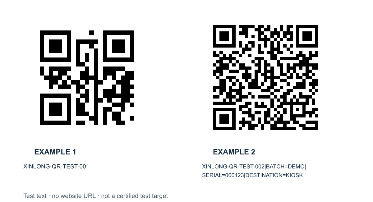
To isolate a screen-reading problem, continue with the guide to reading barcodes from phone screens. For broader requirements, start with the barcode scanner module selection guide.
3. Repeat the test with the front window installed
Compare the sample without a panel and with the glass or acrylic window, bracket, and seals of the final design. The window may introduce reflections, reduce light transmission, or obstruct part of the field of view. No single panel thickness or mounting distance works for every module.
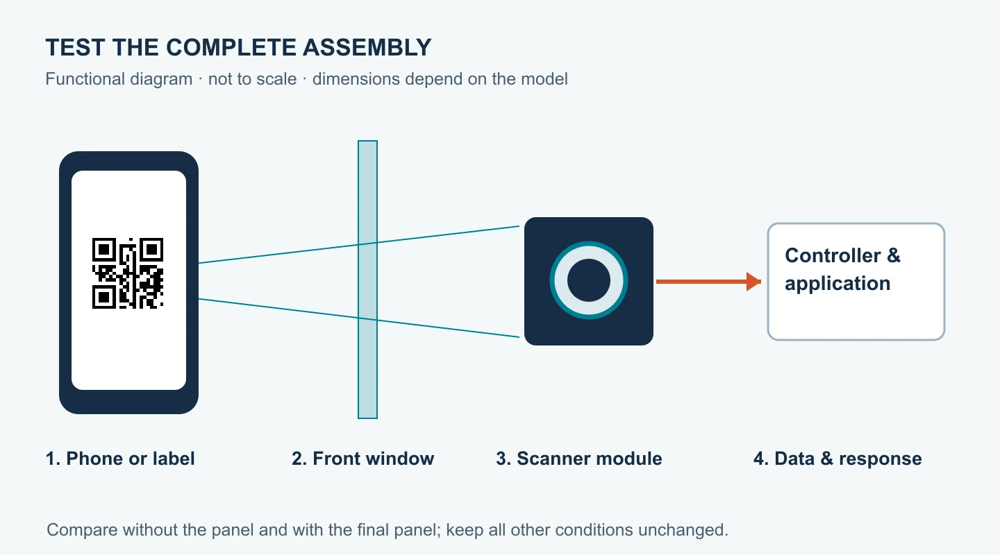
- Check the reading area from positions where users are likely to present a code, rather than testing only at the center.
- Inspect edges, screws, and seals that could obstruct the optical area. Also allow clearance for the connector and the cable's bend radius.
- Repeat relevant conditions with a clean surface and with contamination representative of the planned maintenance interval, without damaging the sample.
- If the reader works without the window but fails behind it, first review the material, angle, shielding, and mounting before changing models.
4. Check the data received by the application
A beep alone is not enough to approve the integration. Compare received text with the expected data and check for missing characters, unexpected suffixes, or duplicate reads. Distinguish decoding time from the time your application takes to validate the data and respond to the user.
USB HID and virtual COM port
For USB HID, confirm the keyboard layout and test the numbers, letters, and symbols your application actually uses. For a virtual COM port, verify the driver where required, data format, and recovery after disconnecting and reconnecting the device. Check compatibility on the final operating system and hardware.
TTL and RS-232
Do not connect a TTL signal directly to an RS-232 port: their electrical levels differ. Confirm the interface variant, pinout, logic level, supply voltage, and communication settings in the documentation. If interface conversion is required, use a circuit appropriate for that design. The USB, TTL, and RS-232 interface comparison explains the selection criteria.
Power supply and operation in the complete system
Repeat the test with the intended power supply, wiring, and peripherals. Observe startup, idle, wake-up, and behavior during terminal activity, always within the datasheet limits. A voltage drop when another load starts can interrupt reading even when the code is valid.
If you plan to use RS-485, a network connection, or wireless communication, also confirm the protocol, addressing, and connection recovery. Having an interface does not mean that every application can communicate with it without configuration.
5. Record comparable results before ordering a batch
Define what counts as an attempt and what constitutes a correct result. One useful measure is the first-attempt correct-read rate: attempts that return the exact data within the agreed time window, divided by total attempts and multiplied by 100. Also record incorrect data, duplicates, and timing; do not reduce every result to “reads” or “does not read.”
For example, 97 correct first-attempt reads in 100 presentations equal 97% under that condition. They do not establish 97% performance across all phones or assemblies. If a critical condition fails, keep it in the issue log and agree on a correction before approving the sample.
| Field | Information to retain |
|---|---|
| Sample | Model, unit identifier, interface, firmware, and configuration |
| Condition | Code, size, phone or paper, distance, angle, lighting, and panel |
| Result | Attempts, exact first-attempt reads, errors, duplicates, and timing |
| Decision | Approved for the defined condition, correction pending, or rejected; responsible person and date |
Use these fields to create your project record, compare candidates with the same procedure, and retain the approved configuration. Before moving to volume production, include the endurance, environmental, and unit-to-unit variation tests required for your equipment.
Which module should you request as a sample?
First shortlist modules by available space, interface, and codes, then validate the candidate. In the catalog, consider the E600 for shallow front panels, the F4100 for vending machine integration, or the XL-F24MINI-NFC for compact panels with optional NFC. These are starting points for evaluation, not a guarantee that any version will suit your application.
Common questions before sample approval
Is testing one phone enough?
One phone does not cover the variation among users. Choose phones and conditions representative of your users, and document what you tested. Expand the set if results differ by screen, brightness, or screen protector.
Can I approve the reader before making the final window?
You can shortlist modules on the bench, but repeat the optical tests with the final panel and mounting position before completing the integration.
Does a module that reads payment QR codes process the payment?
Reading a QR code captures data. Payment authorization and processing are handled by the integrated payment system; they should not be inferred from the module's ability to read a code.