DPM Direct Part Marking Reading Guide: Reliable Reads on Metal and Plastic Parts
Automotive parts, machined hardware, PCBs and medical instruments increasingly carry their identifier on the part itself — no label to peel. Reading a DPM (Direct Part Marking) code reliably is a system problem: marking method, illumination, optics and decode software all have to line up. This guide follows that chain.
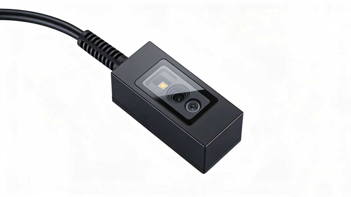
An industrial fixed-mount reader at a production station · a fixed station and steady takt come first
1. What DPM Is: Four Marking Methods
What the surface looks like depends on how the mark was made. Four methods cover most production:
Laser marking
The laser ablates or alters the surface, leaving pits or colour-changed dots; consistent and fast.
Dot peen
A hard stylus punches pits tens to a hundred microns deep; tough, corrosion-resistant, common on castings and forgings.
Inkjet
Ink is jetted onto the surface and reads by ink-to-substrate contrast; cheap, but solvent or abrasion removes it.
Electrochemical etching
An electrolyte and stencil etch a conductive surface; flat edges, even depth, typical on bearings and round parts.
2. Why DPM Is Hard to Read
A DPM code is part of the material, and the problems stack:
- Low contrast: laser and dot-peen marks image by geometry, not colour, so pits and surface look almost identical.
- Curved surfaces: on cylinders and cones the cells stretch, turning the Data Matrix grid trapezoidal or arced.
- Specular glare: polished stainless and chrome bounce light into the lens and blow out part of the code.
- Depth coupled to light direction: the same dot-peen code reads well under grazing light from one side and vanishes when the light moves.
- DPM-specific distortion: uneven cells, burrs and crowded quiet zones make general-purpose decoders fail.

An AI-decoding industrial module built for low-contrast and damaged codes
3. Hardware: Illumination Comes First
With DPM, fix the light before the camera:
- Low-angle / dark-field: light skims the surface so pits cast shadows, manufacturing the geometric contrast — first choice for dot peen.
- Coaxial: suits flat, colour-changed laser marks; on mirror-like parts it returns as a bright patch.
- Multi-angle / dome: several directions even out shadows on curved faces, the practical option for complex shapes.
- Polarisation: cuts the specular component and keeps the diffuse signal.
Balance the optics too:
- Depth of field and working distance: part height varies under the takt, so it must cover the whole marking zone.
- Resolution and field of view: each smallest cell needs several pixels, sized from the marking plus location tolerance.
- Exposure and fusion: short exposures stop glare blowing out the code; fusing frames recovers weak signal.
4. Software: Decoding Built for DPM
General decoders assume clean cells and plenty of contrast — what DPM withholds. A DPM pipeline usually does three things: image enhancement (denoising, local contrast stretching, adaptive thresholding), geometric correction (grid fitting, distortion correction, quiet-zone location), and decode algorithms tuned for dot patterns and low contrast, with an AI model on some options to rescue poor images. Enhancement serves the decoder: stretching noise along with the signal smears the code just as badly.
5. Validation: Grades Plus First-Time Read Rate
“It scans” is not enough; production needs repeatability:
- ANSI/ISO grade: printed codes are graded under ISO/IEC 15415, DPM under ISO/IEC 29158 (the DPM grade), scoring contrast, cell modulation and axial uniformity.
- First-time read rate: reading at a fixed station and takt and counting the share that succeed on the first attempt — how well the system works at that station.
Sample different batches, orientations and surface conditions, not one golden part.
6. Troubleshooting Order When a Code Will Not Read
- Light first: move to low-angle or multi-angle illumination, add polarisation on reflective parts.
- Then the mark: magnify it — enough contrast, intact quiet zone, no missing cells.
- Then the optics: working distance, depth of field and field of view against the real mark size.
- Then exposure: fix exposure and add frame fusion so auto-exposure stops drifting.
- Only then the decoder: enhancement strength, threshold, algorithm profile.
- If it still fails, revisit the process: marking depth, cell size, surface finish, mark position.
Solve the physical problem first instead of asking software to compensate for the optics.
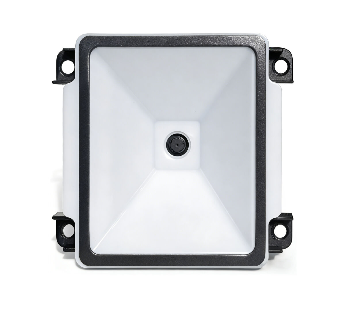
Embedded engines and fixed-mount readers side by side on a production station
7. Marking Method, Material, Difficulty and Recommended Setup
| Marking method | Typical materials | Main reading difficulty | Recommended setup |
|---|---|---|---|
| Laser marking | Stainless steel, aluminium, hard plastics | Low contrast, uneven colour change, specular glare | Coaxial or multi-angle light + polarisation, short exposure |
| Dot peen | Castings, forgings, carbon steel | Varying depth, burrs, directional shadows | Low-angle dark-field light, multi-directional fill |
| Inkjet | Plastics, anodised surfaces, packaging | Fading, solvent removal, dot spread | Diffuse or ring light; guard against contamination |
| Electrochemical etching | Bearing steel, tooling, round metal parts | Curved-surface distortion, low contrast | Multi-angle light + grid distortion correction |
Related products
G53-AIAI-decoding industrial scan module
G4503Industrial fixed-mount scanner
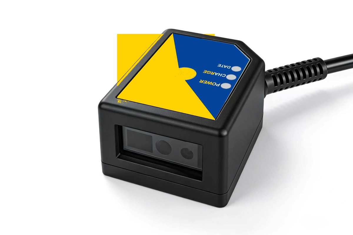 XL-G1103Fixed-mount scan engine
Related articles
Not sure which setup reads your DPM codes?
Send the material, marking method, cell size and takt time — free sample testing against your own parts.
📞 Contact Xinlong IoT