Laser-marked barcodes on PCBs can be difficult to read when the marking and its background look too similar in the reader's image. Reflections, surface finish and installation angle can also obscure the code, even when the mark is visible to the human eye.
For one customer's yellow-toned copper-surface PCB sample, Xinlong configured an F31-BW scan engine with a custom blue LED. According to project feedback, red and white illumination produced poor reading results on the sample, while the custom blue-LED configuration could read it. The demonstration video shows the blue-LED setup; it does not show a controlled comparison of all three lighting colours.
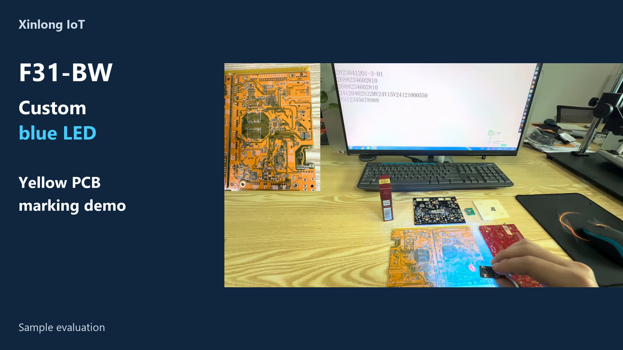
Start with the contrast in the camera image
A reader must distinguish the marked areas from their background. Decoding can become difficult when both areas are bright or both are dark and their recorded grey levels are close. Local overexposure can also obscure the boundaries between small code elements.
Metallic or surface-treated PCBs can reflect light strongly in particular directions. A small change in reader position may move a bright reflection across the marking. Laser-induced texture, oxidation or surface roughness can also affect the reflected signal; the actual mechanism depends on the material and marking process.
Inspect the complete code area, the separation between its elements and any saturated regions. Confirm the decoded data on the host as well. Making the whole image brighter does not necessarily increase the difference between the mark and its background.
How blue light can change a PCB image
The signal recorded by the camera depends on the illumination spectrum, the reflectance of the background and marked areas, the transmission of the lens and any filters, and the image sensor’s spectral response. Exposure, gain and viewing angle also affect the recorded image.
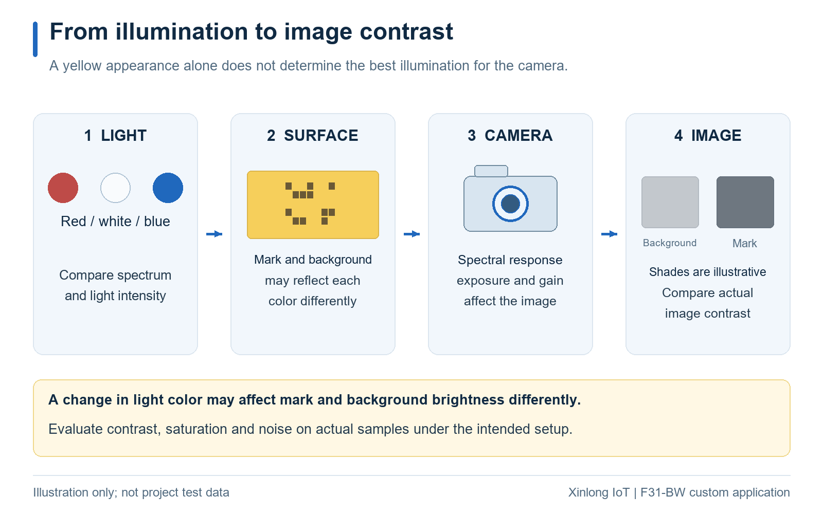
On some yellow-toned surfaces, switching to blue illumination may make the difference between the marked and unmarked areas easier for the camera to distinguish. This is a plausible optical explanation to investigate for the F31-BW project. Check the captured image and decoded output to see what happens on the actual sample.
Colour alone does not establish whether a surface is bare copper, plated, covered by solder mask or otherwise treated. Different production batches and processes may respond differently. Blue illumination must be evaluated with representative samples rather than assumed to work for every yellow PCB.
The custom LED changes the imaging conditions. Illumination and decoding capability are separate evaluation factors; changing the light source alone does not establish that the decoding algorithm has changed.
Adjust illumination and viewing angles together
Even with a suitable light colour, reflections may cover the code. When specular reflection enters the lens, glare can conceal marked features. Adjusting the illumination or viewing angle may move that reflection away from the camera while preserving useful detail.
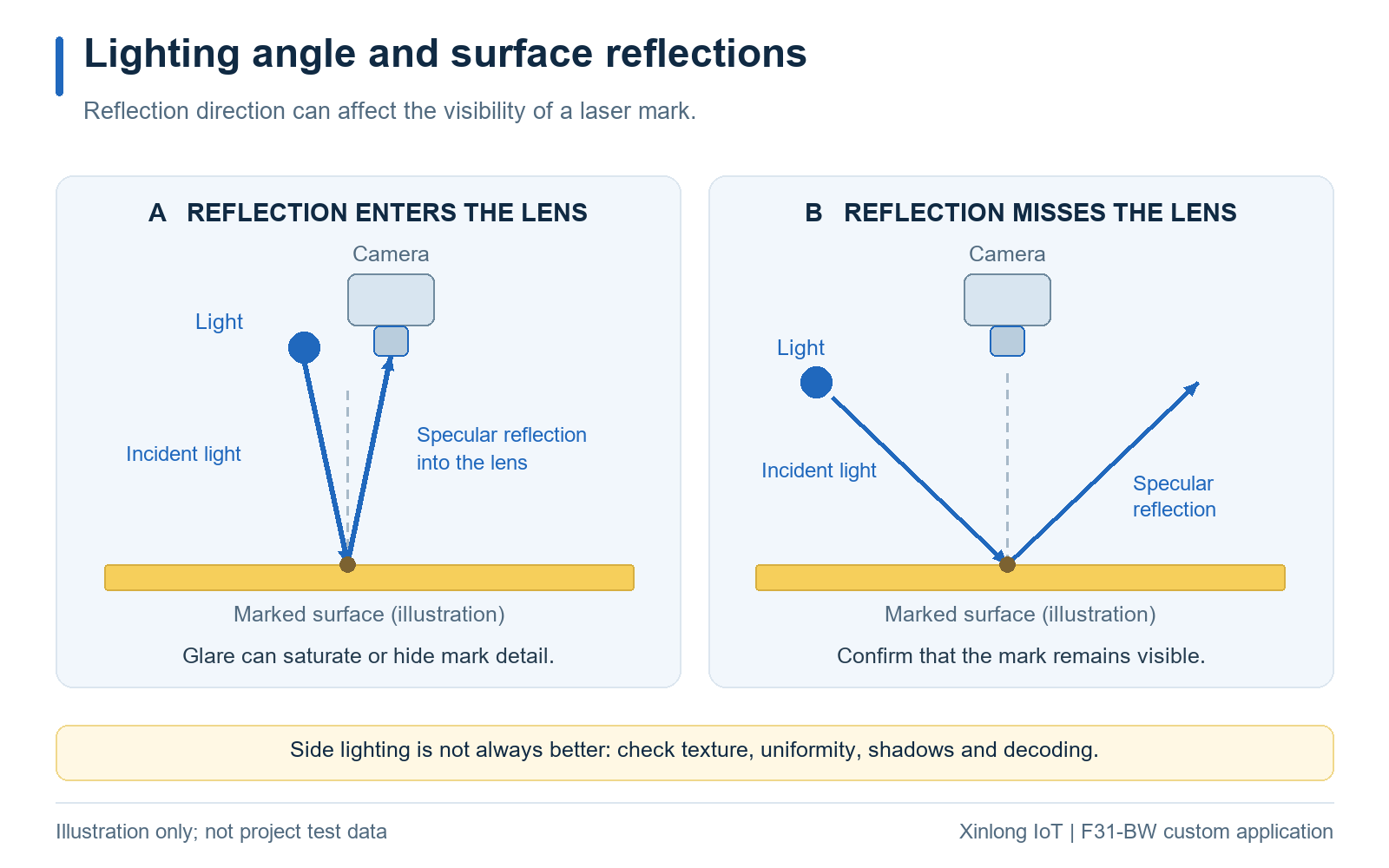
Choose an angle that can be reproduced within the equipment's mechanical constraints. Keep enough field of view for the entire code and its required surrounding area. After installing the actual protective window, repeat the test to check window reflections, light transmission and mounting tolerances.
If the useful signal under blue light is weak, a longer exposure or higher gain involves trade-offs. Exposure time affects motion blur, while gain affects image noise. A successful static read at a fixed workstation should be followed by a test at the required operating speed.
Compare red, white and blue lighting in two stages
First, perform an initial comparison. Use the same samples, mounting distance and viewing angle. Fix exposure and gain, then record the images and decoded outputs for each light colour. Record the light-source drive settings too. Equal exposure does not mean equal optical power, so this stage alone cannot establish which colour is best.
Next, tune each candidate separately. Within the acceptable limits for saturation, noise and operating speed, adjust exposure, gain and any permitted lighting angle for each colour. Compare the reading results with repeatable settings.
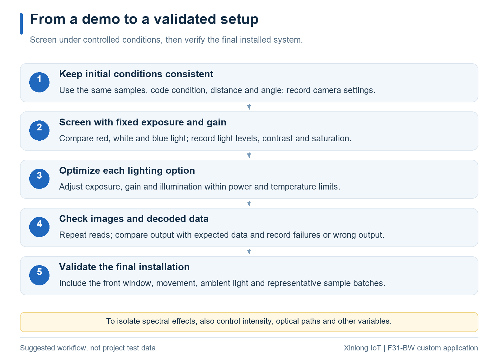
Keep the following information for selection and repeat testing:
Scroll horizontally to view all columns. Focus the table to use arrow keys.
| Test item | What to record |
|---|---|
| Samples | ID, batch, surface treatment, laser-marking process and contamination condition |
| Barcode | Symbology, overall dimensions, smallest element size and expected decoded string |
| Installation | Reading distance, camera and lighting angles, fixture position and protective window |
| Imaging | Light version, drive settings, exposure, gain and representative images |
| Results | Number of attempts, correct reads, failed samples and the method used to report read time |
| System | String received by the host, interface settings and association between the trigger and the part |
Count a read as correct when its decoded string matches the expected data. Indicator lights or beeps can help observe status, but their meaning should be checked against the relevant firmware documentation. If the project requires a formal barcode quality grade, use the applicable standard and verification equipment. A reading demonstration does not replace a quality assessment.
Assess the total integration cost
For a workstation with defined space, reading distance and sample range, evaluating illumination and mechanical conditions early can help identify a suitable hardware configuration. In this project, the F31-BW custom blue-LED version was evaluated for a particular surface and marking condition.
Compare the scan engine, lighting customization, power and thermal requirements, fixture, commissioning and adaptation for later production batches. Also test representative boards, allowable position variation and the required operating cycle. The video demonstrates a sample setup; production stability requires recorded testing under production conditions.
Reassess the light colour and geometry when a sample has a different finish, stronger reflections or shallower marking. Compare other reading hardware when necessary.
What to provide for a sample evaluation
For a difficult yellow-toned, reflective or low-contrast PCB marking, share representative physical samples and clear photographs. Include the barcode symbology and dimensions, surface treatment, available reading distance and angle, motion and cycle requirements, and host interface.
If you have already tried red, white or other illumination, retain the original images and settings. Xinlong can use this information to assess an F31-BW custom illumination configuration and the integration conditions for your workstation.
Watch the custom blue-LED PCB demonstration
View the standard F31-BW product page
Read the PCB laser-marked barcode scanning guide
Request an OEM sample evaluation