Decoding Laser-Engraved PCB Barcodes: You Don't Always Need an Expensive Vision System
A laser-engraved Data Matrix on a PCB is a low-contrast mark by design: the laser removes solder mask or burns it dark, so the code reads by surface geometry rather than by ink on paper. That explains why general-purpose modules struggle, and why a vision system is often more tool than the job needs.

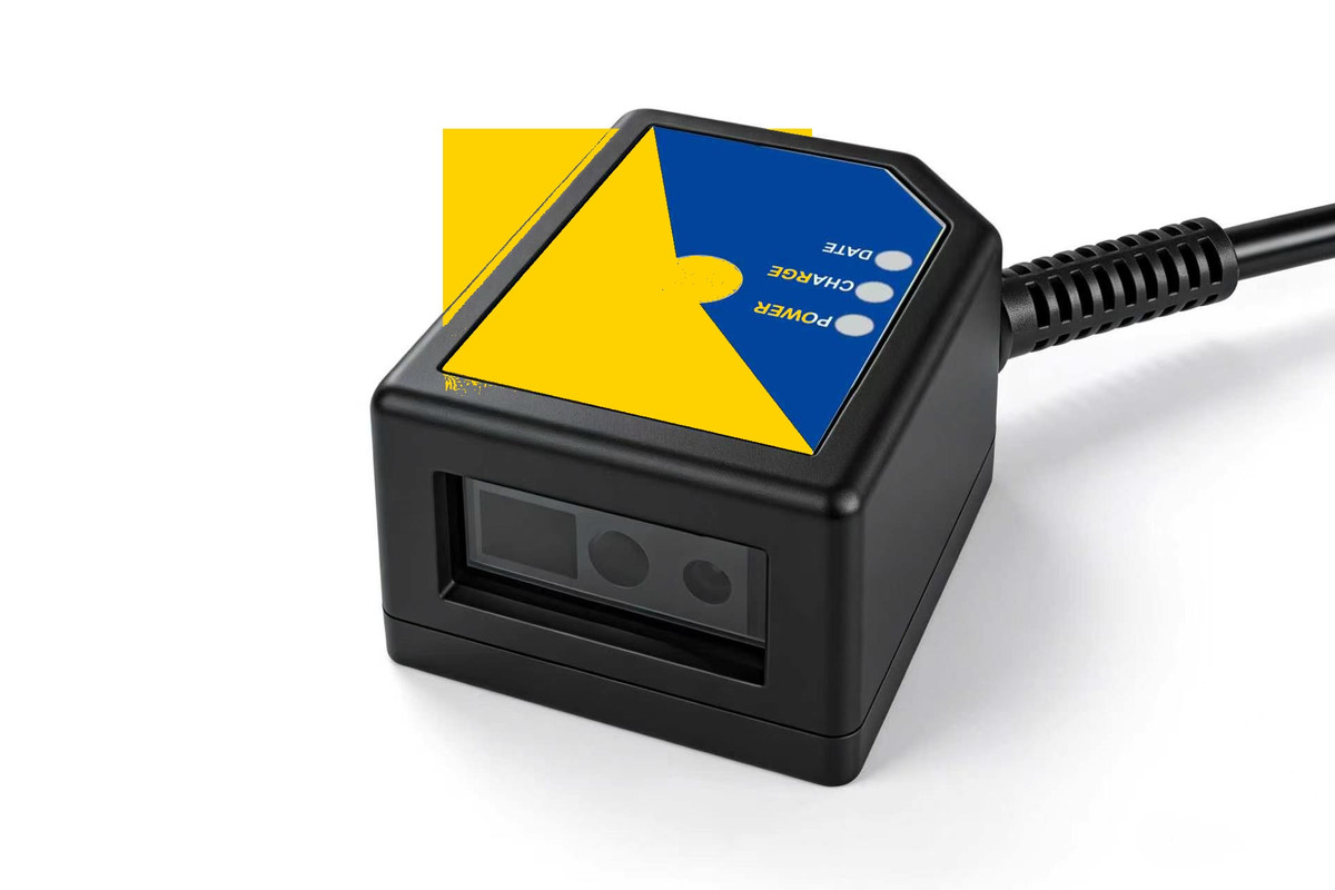
A 16.8 mm fixed-mount reader · built to sit beside the probe field of a test fixture
1. What the Mark Really Looks Like
On FR4 with green or black solder mask, the laser either ablates the mask to expose copper or carbonises it into a dark, matte dot. Both variants produce cells that differ from the background by a few grey levels and by tens of microns of depth. Under diffuse light the code can look almost uniform; under grazing light the same code separates cleanly.
Three consequences follow: the light angle matters more than resolution; a decoder tuned for printed labels rejects valid cells as noise; and the same code can read differently on two panels from different suppliers.
2. Three Tiers of Hardware
| Tier | Typical use | Where it stops |
|---|---|---|
| General 1D/2D module | Labels, screens, tickets | Low-contrast laser marks |
| Light-industrial DPM reader | One mark per part, fixed distance | OCR, multi-side, damaged codes |
| Full vision system | Inspection, OCR, multi-side | Cost, footprint, integration time |
The middle tier is the one most often skipped in the specification, and on a PCB test fixture it is usually the correct answer.
3. Where the Middle Tier Wins
If the job is one Data Matrix per board, at one fixed position and one working distance, what is needed is a reader with a DPM-aware decoder, controlled light and a body small enough to mount. A lens mount, an industrial PC and a vision licence add cost and integration work without improving the read.
It also fails predictably: damaged mark, code below the optics limit, or part height beyond the depth of field. Those are mechanical answers, not software ones.
4. Four Things to Measure First
- Cell size. Measure the smallest module, not the code: modules per millimetre decide what the optics can resolve.
- Contrast. Photograph the worst mark under the intended light; a few grey levels rule out a general-purpose module.
- Height variation. Measure the code surface across the batch, connectors included; that range is your depth of field.
- Cycle budget. Measure decode time at the real exposure.
5. Integration Notes That Decide the Result
- Fix the distance. A bracket at a repeatable height beats a better sensor at a variable height.
- Control the light. A closed lid is free contrast: no daylight, identical cycles.
- Keep the window clean. Flux aerosol settles on it; mount the reader where it can be wiped.
- Respect the supply. A 5 V rail shared with relays will sag — use its own regulator and a short FPC.
- Trigger from the tester. A hardware trigger tied to the clamp signal removes a class of missed reads.
6. When You Do Need the Vision System
Buy the bigger tool when the job genuinely needs it: OCR on laser text, several sides of an assembly, mark grading, or codes below the resolving limit of a fixed reader. The mistake also runs the other way — paying for a vision system to read one code at one distance.
7. A Concrete Example
The G4503 is a light-industrial DPM reader in a 49 × 21 × 16.8 mm body, 75 g, with a 1600 × 1200 sensor, a 30–300 mm working range and a 42° × 31.5° field of view. It reads laser-engraved PCB marks and connects over USB, TTL-232 or RS-232 on a single 5 V supply drawing under 200 mA through an 8-pin FPC. No IP rating, no Ethernet, no opto-isolated I/O.
For fixture design, the G4503 product page carries the brochure, the specification sheet and a STEP model, so the pocket and clearance cone can be checked in CAD.
Have a laser-marked board that will not read reliably?
Send the marking method, cell size and working distance — we test your samples and report the first-time read rate.
📞 Contact Xinlong IoTRelated products
G4503Ultra-thin fixed-mount DPM scanner
 G53-AIAI-decoding industrial scan module
 XL-G1103Fixed-mount scan engine