How to Choose a Barcode Scanner for PCB Automated Test Jigs
A PCB becomes traceable when its serial number reaches the tester's database. On most SMT lines that happens inside the fixture: the board is clamped, the probes close, and a scanner in the jig reads a Data Matrix before the test starts.

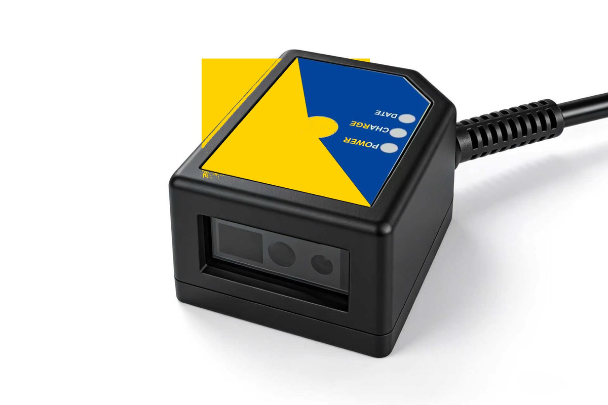
A fixed-mount reader inside a test fixture · the board position, not the scanner, sets the working distance
1. What a Fixture Asks For
An ICT or FCT fixture is a repeatable machine, and the scanner is one of its components:
- One fixed reading position — the board lands in the same place every cycle.
- A short working distance — the code sits a few centimetres under a closed lid.
- Hundreds of triggers per shift — one read per cycle, started by the tester.
2. Space Comes Before Resolution
Most fixture designs fail on height, not on optics. The gap between the probe plate and the lid, the clamp travel and the probe wiring leave a thin slot for anything that is not a probe. A reader 40 to 60 mm tall needs a pocket cut into the fixture; a reader 16.8 mm tall can sit on the plate beside the probe field.
Two dimensions decide the fit: the height above the mounting face, and the clearance cone in front of the window, where the field of view must clear the frame and the clamp.
3. What Decides Read Rate
- How the code was made. A printed label and a laser-engraved mark on black solder mask are different optical problems; the laser mark reads by geometry, not colour.
- Depth of field. Board thickness, connector height and clamp pressure move the code by a few millimetres, and the depth of field has to cover that movement.
- Field of view. It must cover the code plus the board's placement tolerance, with margin.
- Cycle time. Exposure and decode must finish inside the tester's handshake window.
- Light. A closed lid is an advantage: it removes daylight and makes every read comparable.
4. Why a Vision System Is Often Too Big a Tool
A full vision system — industrial camera, lens, dedicated lighting, industrial PC and a software licence — earns its cost when the job needs OCR, several sides of a part, or defect inspection on the same image. For one fixed Data Matrix on one fixed board, most of that capability is never used, while the integration effort and the footprint stay.
A DPM-capable fixed reader covers the single-code case with housing, light and decoder in one part; the trade-off is that it will not inspect solder joints or read a destroyed code.
5. Selection Checklist
| Requirement | What to check |
|---|---|
| Height | Body height against the lid gap, with 1–2 mm clearance |
| Working distance | Window to code at the closed position, plus board tolerance |
| Depth of field | Covers board thickness and clamp movement |
| Field of view | Code size plus placement tolerance, with margin |
| Code type | Laser-engraved DPM, printed label, or both |
| Interface | USB, TTL-232 or RS-232 into the tester |
| Mounting | FPC or cable exit direction, bracket clearance |
6. Where the G4503 Fits
The G4503 is built for this slot: a 49 × 21 × 16.8 mm body, 75 g, a 1600 × 1200 sensor, a 30–300 mm working range and a 42° × 31.5° field of view. It reads laser-engraved codes on PCB surfaces and connects over USB, TTL-232 or RS-232, drawing under 200 mA from a single 5 V supply through an 8-pin FPC.
Two limits are worth stating plainly: no IP rating, no Ethernet port and no opto-isolated I/O. If the fixture needs those, another model in the range is the right answer.
Brochure, specification sheet and a STEP model of the housing are on the G4503 product page.
7. Validate on Your Own Boards
Send five to ten boards, including the worst marks, and run 200 cycles at the real working distance; count first-attempt reads, not retries.
Designing a fixture around a scanner?
Send the board thickness, code type, working distance and lid gap — we will check the geometry against the G4503 3D model and quote a sample.
📞 Contact Xinlong IoTRelated products
 G4503Ultra-thin fixed-mount DPM scanner
 G53-AIAI-decoding industrial scan module
 XL-G1103Fixed-mount scan engine