A barcode that reads reliably on the bench can become difficult to decode when it moves through a machine. The captured image may show slanted edges, stretched code modules or blurred bars. Understanding global shutter vs. rolling shutter for barcode scanning helps separate these effects and plan a useful sample test.
The sensor's exposure method is one part of that decision. Exposure time, illumination, image scale, focus and the decoding algorithm also affect the result. This guide explains what each shutter method does and how to evaluate an embedded scan engine or fixed mount barcode reader with moving targets.
1. Exposure and readout are separate operations
During exposure, each pixel collects light over a period of time. During readout, the captured signal is transferred through the sensor electronics. A camera can expose its pixels together and still read the image data out row by row.
Keep three timing parameters separate when discussing a barcode scanner:
- Exposure time: how long a pixel integrates light for one image.
- Row timing and readout: when different rows capture the scene and how the data leaves the sensor.
- Frame period: the interval between successive frames. Frame rate is its reciprocal.
A nominal rate of 60 frames per second corresponds to a frame period of about 16.7 ms. It does not mean the exposure must last 16.7 ms. Exposure and readout may overlap, depending on the sensor and operating mode. Confirm the supported timing and controls for the actual scanner module.
2. How global shutter and rolling shutter expose an image
Global shutter: a shared exposure window
With a global shutter, pixels across the image start and end exposure at approximately the same time. In a typical implementation, the captured signal is then stored while the image is read out. The rows therefore represent a common time window, even when their data is transferred sequentially.
This reduces the geometric distortion caused by different rows capturing a moving object at different times. It does not freeze all motion: the object can still move during that shared exposure window.
Rolling shutter: exposure windows shift from row to row
With a rolling shutter, rows start and finish exposure at successive times. Each row can have the same exposure duration while its exposure window is offset from the previous row. A moving object may occupy a different position when each row captures it.
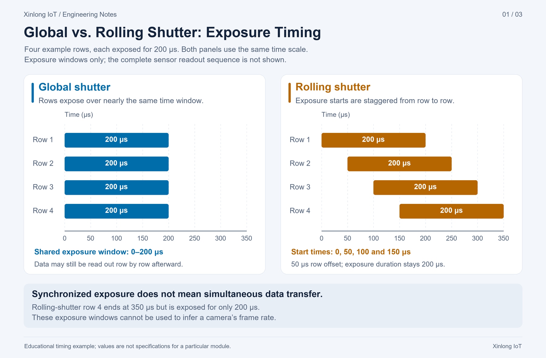
In Figure 1, every illustrated row has a 200 μs exposure. The rolling shutter rows start at 0, 50, 100 and 150 μs, so their exposures end at 200, 250, 300 and 350 μs. The global shutter rows all expose from 0 to 200 μs. These four-row examples explain the timing relationship; they are not sensor specifications or frame-rate measurements.
| Question | Global shutter | Rolling shutter |
|---|---|---|
| When do rows expose? | Approximately the same time window across the image | Successive time windows across the image |
| Can motion change the geometry between rows? | Row timing distortion is reduced | Yes; its form depends on motion direction, row timing and scene geometry |
| Can exposure cause motion blur? | Yes | Yes |
| What still needs testing? | Exposure, lighting, focus, code image size and decoding | The same factors, plus the effect of row timing on the moving target |
3. Rolling shutter distortion and motion blur have different causes
Rolling shutter distortion appears when rows capture a moving scene at different times. For example, a horizontally moving square may look slanted. Other combinations of motion and scan direction can stretch or compress the target. Shortening each row's exposure can reduce blur while leaving distortion from the time offsets between rows.
Motion blur occurs when the target image moves during a pixel's exposure. A narrow bar or QR code edge spreads across the image, reducing edge contrast. Both global shutter and rolling shutter cameras can produce this blur. A rolling shutter image may contain distortion and blur together.
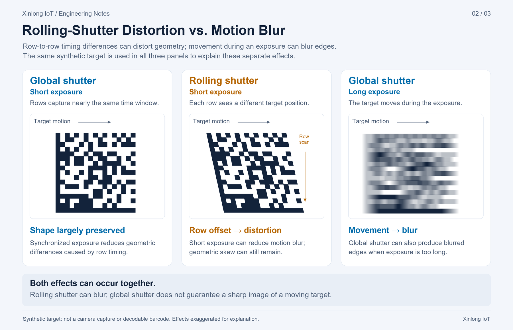
When reviewing a failed read, inspect the captured image if the module provides that function. Slanted or compressed code geometry suggests a timing effect; smeared edges suggest exposure-related motion blur. Defocus, reflections and low resolution can also soften edges, so a blurred-looking image alone does not identify the cause.
4. Estimate motion during exposure for moving barcodes
For approximately constant motion parallel to the target plane, the distance the target travels during exposure is:
d ≈ v∥ × t_exp

d     = target-plane displacement during exposure
v∥    = target speed relative to the camera, parallel to the target plane
t_exp = exposure time
Use compatible units. A speed of 1 m/s equals 1 mm/ms. At that speed, a 0.1 ms exposure corresponds to 0.1 mm of target travel; 0.5 ms corresponds to 0.5 mm; and 1 ms corresponds to 1 mm.
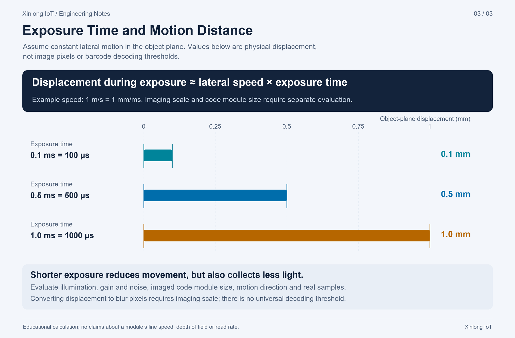
These values describe physical displacement at the target plane. Converting them to an image blur length requires the imaging scale. For a locally front-facing target, a first estimate is blur in pixels ≈ displacement in mm × pixels per mm. Perspective, rotation or motion toward the camera requires a more detailed model.
For example, if the target moves 0.1 mm during exposure and the local image scale is 20 pixels/mm, the estimated image movement is 2 pixels. This is a calculation example, not a readable/unreadable threshold. The effect depends on the code's module size in pixels, motion direction, contrast and decoding conditions.
Compare the estimated movement with the smallest bars or code modules along the direction of motion, then test the real sample. The barcode scanner field of view guide explains scan area and pixels per module. A larger field of view generally places fewer pixels across the same small code when the sensor resolution and imaging geometry are otherwise comparable.
5. Choose exposure time together with illumination
A shorter exposure reduces motion during capture, but also collects less light under the same conditions. Increasing gain may brighten the image while making noise more visible. Added illumination can help, although reflections from a glossy label, protective window or curved surface can reduce usable code contrast.
Set the working distance, focus, code image size and lighting geometry before comparing shutter types. Record the exposure behavior as well. Automatic exposure may select a different duration when the label color or ambient light changes. Where supported, test a controlled exposure or an exposure limit across the expected operating range.
Short lighting pulses can help limit the effective capture interval in a suitably synchronized system. For a rolling shutter sensor, pulse timing must account for which rows are exposing. A short flash at the wrong time can illuminate only part of the image. Confirm sensor mode, trigger timing and lighting compatibility before choosing this approach.
For conveyor integration, test the actual line speed, code orientation and capture position. For a kiosk, test both a stationary code and the hand motion used to present it. A global shutter barcode scan engine can help preserve moving code geometry, but the shutter label alone does not establish reading performance for either application.
6. Validate the scanner with the actual motion and code samples
A useful evaluation states the operating conditions and a measurable acceptance rule. Test more than one good label, and include the installation window or enclosure intended for the finished device.
| Test item | Record and verify |
|---|---|
| Code samples | Symbology, payload, overall size, module size, quiet zone, print or screen quality, and surface material |
| Installation | Working distance, field of view, focus, angle, protective window and code position within the image |
| Motion | Speed range, direction relative to the image rows, orientation, acceleration and time spent in the usable reading area |
| Image acquisition | Exposure or automatic exposure behavior, gain, illumination, trigger mode and available capture timing |
| Reading results | Successful reads over a stated number of presentations, correct decoded payload, read latency, timeouts and duplicate reports |
| Operating variation | Ambient light, label variation, mounting tolerance and the final enclosure |
Define a successful presentation before the test: the correct payload must reach the host within the allowed time and trigger window. Retain failed images where available. Repeat the test after changing exposure or illumination so the comparison has a documented basis.
For an initial sample plan, use the QR scanner module sample validation guide. For hardware selection, review fixed mount barcode readers or discuss an OEM barcode scanner module integration with the device requirements in hand.
7. Common shutter and exposure questions
Does a global shutter eliminate barcode motion blur?
No. Global shutter aligns the exposure windows across the image. Motion during that window can still blur the code. Exposure time, illumination and image scale remain part of the evaluation.
Can a rolling shutter scanner read moving QR codes?
It can under suitable conditions. The result depends on target speed and direction, row timing, exposure, code image size and the decoder. Validate the required operating range with real samples rather than treating the shutter type as a pass/fail rule.
What exposure time should I use for a moving barcode?
Start by estimating target travel with d ≈ v∥ × t_exp, convert it to image movement using the local image scale, and compare it with the code detail. Then test shorter exposures with sufficient illumination. There is no universal exposure setting that guarantees decoding across different codes and installations.
Figures are simplified teaching illustrations. Their timing, motion and image examples describe acquisition principles; they do not specify the performance or controls of any Xinlong product.
Plan a moving barcode sample test
Send Xinlong IoT your code samples, working distance, speed and motion direction, available installation space and host interface. These details help define a scan engine evaluation for the finished device.