How to Integrate an Ultra-Thin DPM Barcode Scanner into Space-Constrained PCBA Test Jigs (ICT/FCT)
When designing an automated PCBA In-Circuit Test (ICT) or Functional Test (FCT) fixture, mechanical and test engineers repeatedly hit the same physical bottleneck: vertical Z-axis clearance. Once the top pressure plate closes, the remaining gap inside the fixture is often less than 60 mm — leaving no room for a conventional C-mount vision camera. Here is how fixture engineers solve tight-clearance PCB traceability with a 16.8 mm ultra-thin fixed-mount DPM scanner.
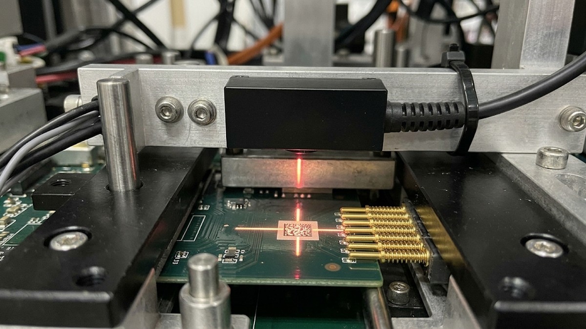
Window-down G4503 inside an ICT fixture, crosshair on a laser-etched Data Matrix code on the PCB
Modern electronics manufacturing requires 100% board-level traceability. Before the pogo pins engage to run electrical tests, the station must capture the laser-engraved Data Matrix (DPM) code etched directly onto the green, black or blue solder mask. A label cannot survive reflow; the mark on the board can. That mark is also the hardest thing in the fixture to read: small cells, low contrast, and a glossy surface sitting a few centimetres from the optics.
1. The 3 Engineering Bottlenecks in PCB Test Fixtures
- Extreme Z-axis space constraints. Standard industrial fixed-mount readers are typically 40–65 mm thick. Mounting one window-down inside a clamshell jig forces engineers to redesign the top acrylic/FR4 pressure plate or cut complex viewing windows.
- Short working distance (50–100 mm). Inside a closed fixture the window sits only 5–12 cm above the board. Many readers lose focus, produce blind spots, or leave specular LED hot-spots at this macro range.
- Low-contrast solder-mask glare. Laser marks on dark resin or glossy green solder mask often sit near 20% print contrast. Without diffused illumination, reflections from adjacent copper pads and gold fingers blind the sensor.
2. Why a 16.8 mm Profile Changes Fixture Mechanics
To clear pneumatic cylinders, guide pins and pogo-pin blocks, the G4503 ultra-thin fixed-mount DPM scanner was built for inline electronics test stations:
- 16.8 mm ultra-slim envelope. A 49 × 21 × 16.8 mm body at 75 g mounts horizontally, window facing down, on a simple L-bracket inside the tightest fixture gaps.
- 2 MP sensor for 5 mil micro Data Matrix. A 1600 × 1200 CMOS sensor resolves ≥ 3.3 mil 1D barcodes and ≥ 5 mil 2D Data Matrix codes down to roughly 20% print contrast.
- Warm-white fill and crosshair aiming. Instead of a harsh red laser that fights green or red solder mask, warm-white illumination plus a crosshair beam gives even contrast across dark and reflective boards inside a 30–300 mm depth of field (optimal at 50–150 mm).
- Single 5 V rail, under 200 mA. Connects to the test PC, ICT controller or PLC over USB, TTL-232 or RS-232 through an 8-pin FPC/cable — no external power adapter in the fixture.
3. When to Choose an Enclosed Scanner vs. a Bare OEM Engine
Two integration paths, depending on how much of the mechanics you want to own:
| Selection criteria | Enclosed fixed scanner (G4503) | Bare AI OEM engine (G53-AI) |
|---|---|---|
| Dimensions & weight | 49 × 21 × 16.8 mm (75 g, rugged housing) | 30 × 15.5 × 13 mm (6.2 g, bare board module) |
| Sensor & optics | 1600 × 1200 CMOS, warm-white LED | 1280 × 800 global shutter, auto red/white LED |
| Target code | Laser-etched PCB DPM, inkjet, paper labels | High-glare metal DPM, curved tubes, damaged codes |
| Interface | USB / RS-232 / TTL-232 (8-pin FPC or cable) | 12-pin FPC (3.3 V TTL / USB) |
| Best for | Bracket mounting inside ICT/FCT test jigs | Custom PCB housing integration and medical analyzers |
4. Download the 3D STEP File and Test Your PCB Samples
Do not guess whether the scanner clears your fixture's pressure pins or reads your specific laser mark.
- For mechanical engineers: download the production G4503 3D CAD model (.STEP) and drop it into SolidWorks, Creo or NX to verify mounting clearance before any bracket is machined.
- For test and automation engineers: send a high-resolution photo or a physical sample of your laser-marked PCBA. Our application engineers record a live decoding video showing the actual working distance and first-pass read rate before you commit to a sample order.
→ Request a G4503 sample or a free PCB read-rate test
Related products
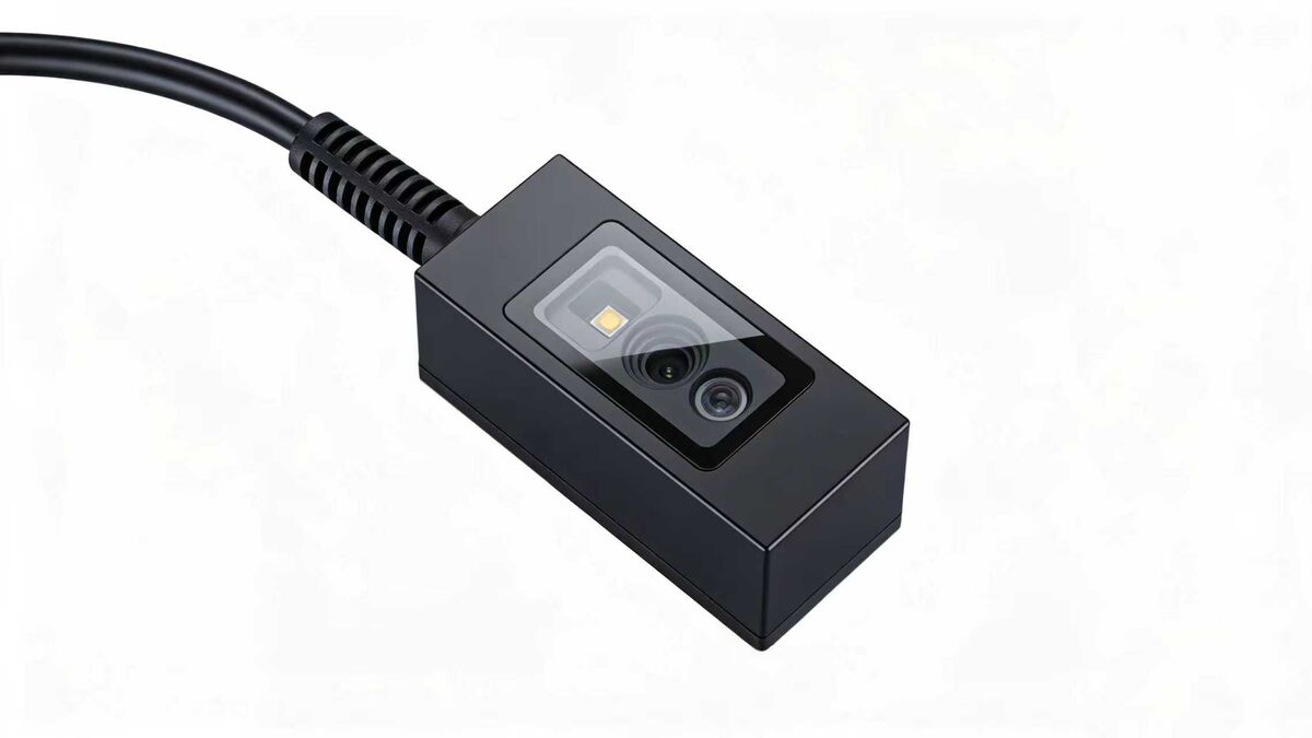 G450316.8 mm ultra-thin fixed-mount DPM scanner
 G53-AIAI OEM engine for hard DPM codes
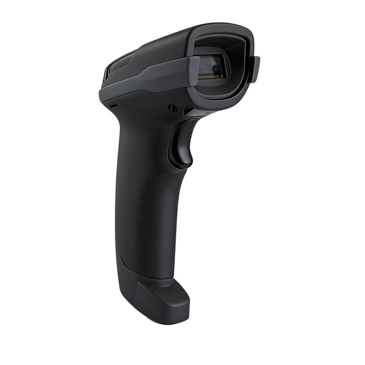 XL-S20-AIHandheld AI DPM scanner for sample checks
Related articles
Not sure which setup reads your DPM codes?
Send the material, marking method, cell size and takt time — free sample testing against your own parts.
📞 Contact Xinlong IoT