Smart lockers, self-service kiosks, access control terminals and visitor management devices may need to scan a QR code on a phone and read an NFC card. An embedded scan module with NFC functionality can bring both input methods into the same device.
Once the hardware is connected, the host application still needs to answer a practical question: when it receives a message, how does it identify whether the data came from a barcode or an NFC card, and route it to the correct business process?
Define the reading requirements, host interface, source identification and card data format before integration. A prototype that reads a code or card successfully may still produce data that does not match the records stored in the backend.
1. Define the reading requirements and system connections
A QR code may contain an order number, collection code, visitor credential or URL. An NFC response may contain a card UID or data from a specified memory area. The application must interpret each result according to the project requirements.
| Item | Barcode / QR code | NFC card |
|---|---|---|
| Reading method | Image capture followed by decoding | Radio-frequency communication |
| Typical content | Text, numbers, URLs or binary data | Card UID or data from a specified memory area |
| Integration considerations | Barcode symbology, character encoding and data length | Card protocol, access permissions and output format |
| Application processing | Parse an order or credential | Match a card record or process the agreed data |
Evaluate modules using the actual codes and cards intended for the project. For example, a smart locker may need to scan a collection code from a phone screen and read an employee card UID. Check screen-code reading performance, supported card types and the card number format already used in the backend as separate requirements.
Reading a card UID does not establish support for reading all of the card's memory. Access to a data area may require authentication, and support depends on the card, module and firmware. A UID is identification data; it does not by itself authenticate the cardholder or establish access permission. Projects that require resistance to card cloning should select an appropriate card authentication mechanism for their risk level.
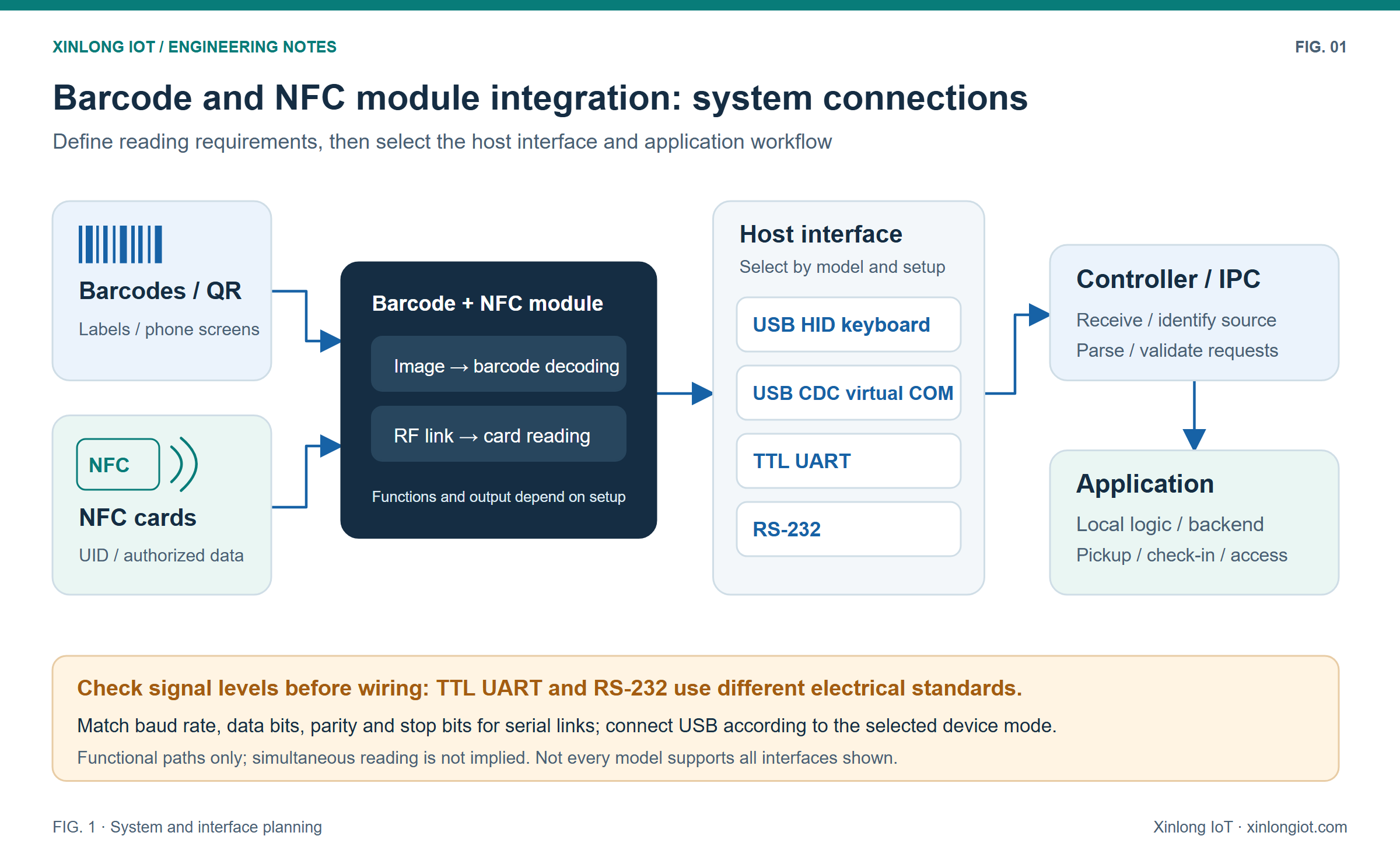
2. Select the interface for the host platform
USB HID keyboard mode delivers the read result as keyboard input. It can suit industrial PC applications with an existing input field. During integration, check input focus, keyboard layout, special characters and terminator handling so that data reaches the intended field with the expected characters.
A USB CDC virtual COM port allows the application to receive and parse the data. Use a receive buffer and the agreed terminator, length field or frame structure to determine when a complete message has arrived. A single read call may return part of one message or several messages together.
TTL UART and RS-232 are common serial connection options for microcontrollers and embedded hosts, but their electrical standards differ. Before wiring, confirm signal levels, pin assignments, power and grounding requirements. For TTL UART, verify the specific logic voltage. Both endpoints must also use compatible baud rate, data bits, parity and stop bits settings.
| Interface | Typical integration method | Main checks |
|---|---|---|
| USB HID keyboard | Receive data through an application input control | Input focus, keyboard layout and terminator handling |
| USB CDC virtual COM port | Open the port and parse the incoming data | Device recognition, receive buffering and message boundaries |
| TTL UART | Connect to a host UART with compatible signal levels | Logic voltage, pin assignments, common ground and serial settings |
| RS-232 | Connect through the appropriate electrical interface | Transmit/receive wiring, level conversion and serial settings |
Consult the relevant model manual to confirm which interfaces and mode changes the product supports.
3. Identify the source of barcode and NFC data
Using data length alone to distinguish barcodes from card numbers can cause misclassification. A rule that treats every ten-digit value as a card number could send a ten-digit collection code into the card-processing workflow.
A project protocol can use an explicit type field or source prefix. The following is a design example that would need to be implemented through supported module settings or host software. It is not the default XL-F42-NFC output format:
BARCODE:PKG20261105001<CR><LF>
NFC:04A1B2C3D4<CR><LF>
Here, BARCODE: and NFC: identify the source. <CR><LF> represents the actual carriage return and line feed control characters, rather than the literal characters shown in angle brackets. If the payload can also contain those terminators, define escaping, a length field or another reliable framing method.
If the module supports separate prefix and suffix settings for barcode and NFC output, those settings may provide the source identifier. With a command-response protocol, the host may instead identify the source from the response type. Choose a method that the actual protocol supports.
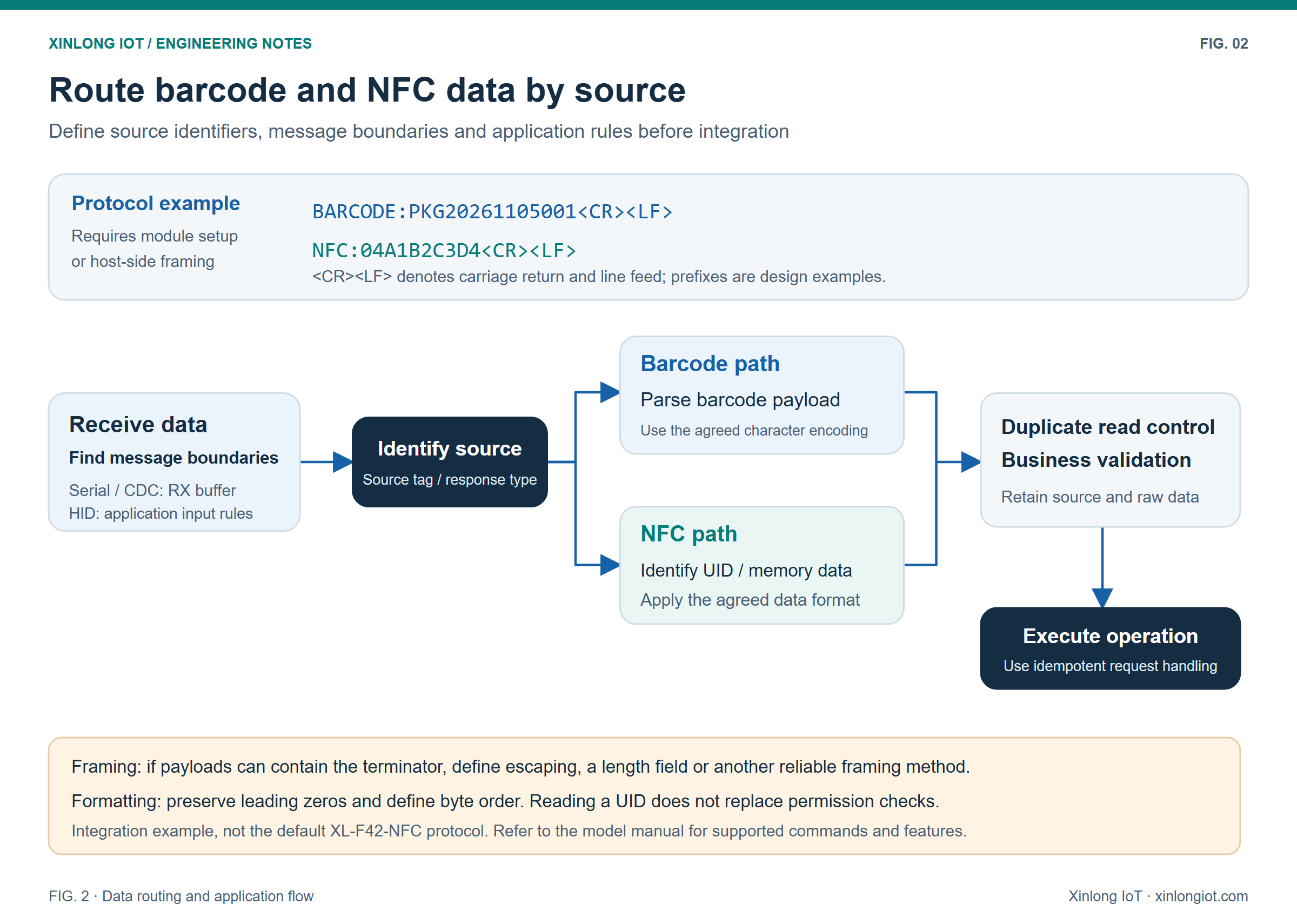
4. Why one NFC card can appear to have different numbers
The same card bytes can appear as different text values under different output settings. When connecting to an existing card database, this difference can be mistaken for a reading error.
Suppose the raw bytes are 12 34 56 78. Concatenating their hexadecimal representation in the original byte order produces 12345678. Reversing the byte order produces 78563412.
The unit of reversal is one byte. Each byte is represented by two hexadecimal characters, so the reversed byte sequence is 78 56 34 12. Reversing the individual characters to produce 87654321 is a different operation.
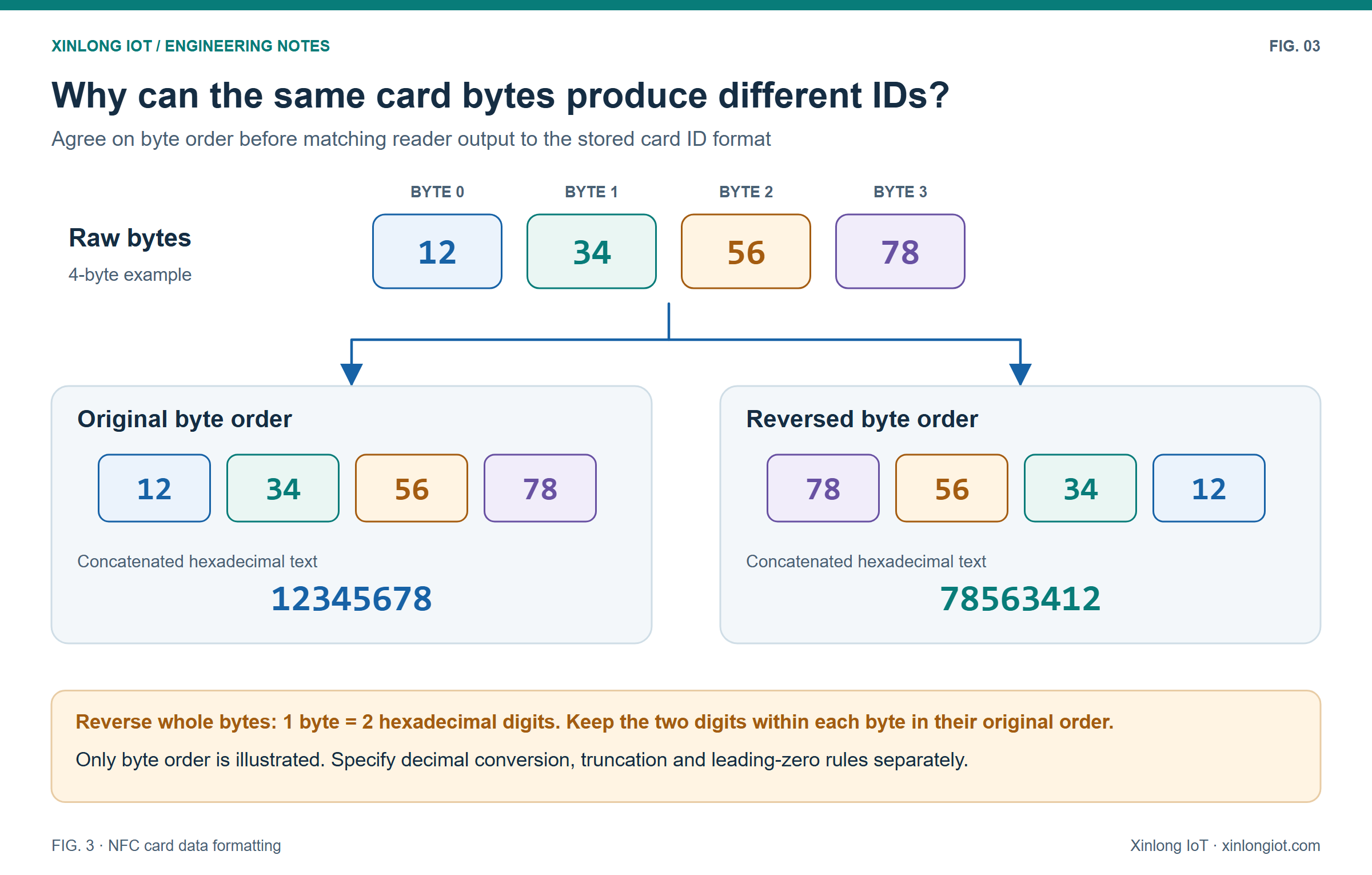
Before connecting to the backend, agree whether the application reads the UID or a data area, uses hexadecimal or decimal output, changes byte order, truncates data or preserves leading zeros. For decimal output, also specify which bytes are converted and the order in which they are interpreted. “Decimal card number” alone does not fully define the conversion.
Preserve the raw bytes and data source, and compare several known cards against the existing database. When storing a card number as an identifier, retain the format required by the application. Storing it as a numeric value may remove leading zeros.
5. Handle repeated reads and repeated transactions separately
When a phone or card remains in the reading area, the module may report the same data repeatedly. Depending on the device capabilities, options may include a repeat-read delay, a single trigger or a requirement to remove the target before reading it again. The host can also implement duplicate read suppression within a defined time window.
Duplicate read suppression and business API idempotency serve different purposes. Suppression reduces repeated reports from the reader. Idempotency controls what happens when the same collection, registration or door-opening request is submitted more than once, helping prevent duplicate charges or repeated state changes.
Keep the data source in the deduplication key where the application requires it. Identical text received from a barcode and an NFC card may represent different operations. Set the time window and repeat-operation policy for the actual workflow.
6. Include error handling in prototype validation
The device should distinguish a read timeout, invalid data format, card authentication failure and communication disconnection. User prompts should help the operator complete the next attempt. Logs should retain the source, status codes and communication details needed for diagnosis, with sensitive data handled according to the project requirements.
| Validation item | What to check |
|---|---|
| Actual QR codes on different phone screens | Reading at the required distances, angles and screen brightness levels |
| Cards used in the project | Card protocol, UID, memory access permissions and output format |
| Alternating barcode scans and card reads | Correct source identification and routing |
| Targets held in place and repeated operations | Duplicate read suppression and business idempotency |
| Disconnection, timeout and recovery | Recovery of data reception and handling of incomplete messages |
| Final enclosure and mounting panel | Effects of the scan window, nearby metal and antenna installation |
Repeat the checks after final assembly. Scan-window transmission and reflections, metal near the NFC antenna and the actual operating distance can make the finished device behave differently from a bare module on the bench.
For a combined barcode and NFC device, document the reading targets, output format, message boundaries and error states before interface development. Then validate the full application workflow using real samples. This helps reveal card number conversion, source routing and repeat-operation issues early in the project.
Terminology: UID — Unique Identifier; UART — Universal Asynchronous Receiver/Transmitter; CDC — Communications Device Class; HID — Human Interface Device. The interfaces and protocol examples in this article describe integration methods. Product support must be confirmed in the documentation for the specific model.
Prepare a barcode and NFC integration review
For an F42-NFC module evaluation, prepare actual QR codes, card types, the host interface, known card-number examples and an enclosure drawing. Confirm the protocol and output format before integration.
F42-NFC application and selection guide · Scanner interface selection · QR module sample validation