A fixed-mount barcode scanner can decode a label while the production application still has an empty serial-number field. The missing step may be an output setting, an incomplete message, a rejected payload or a result that arrived after the workpiece cycle closed.
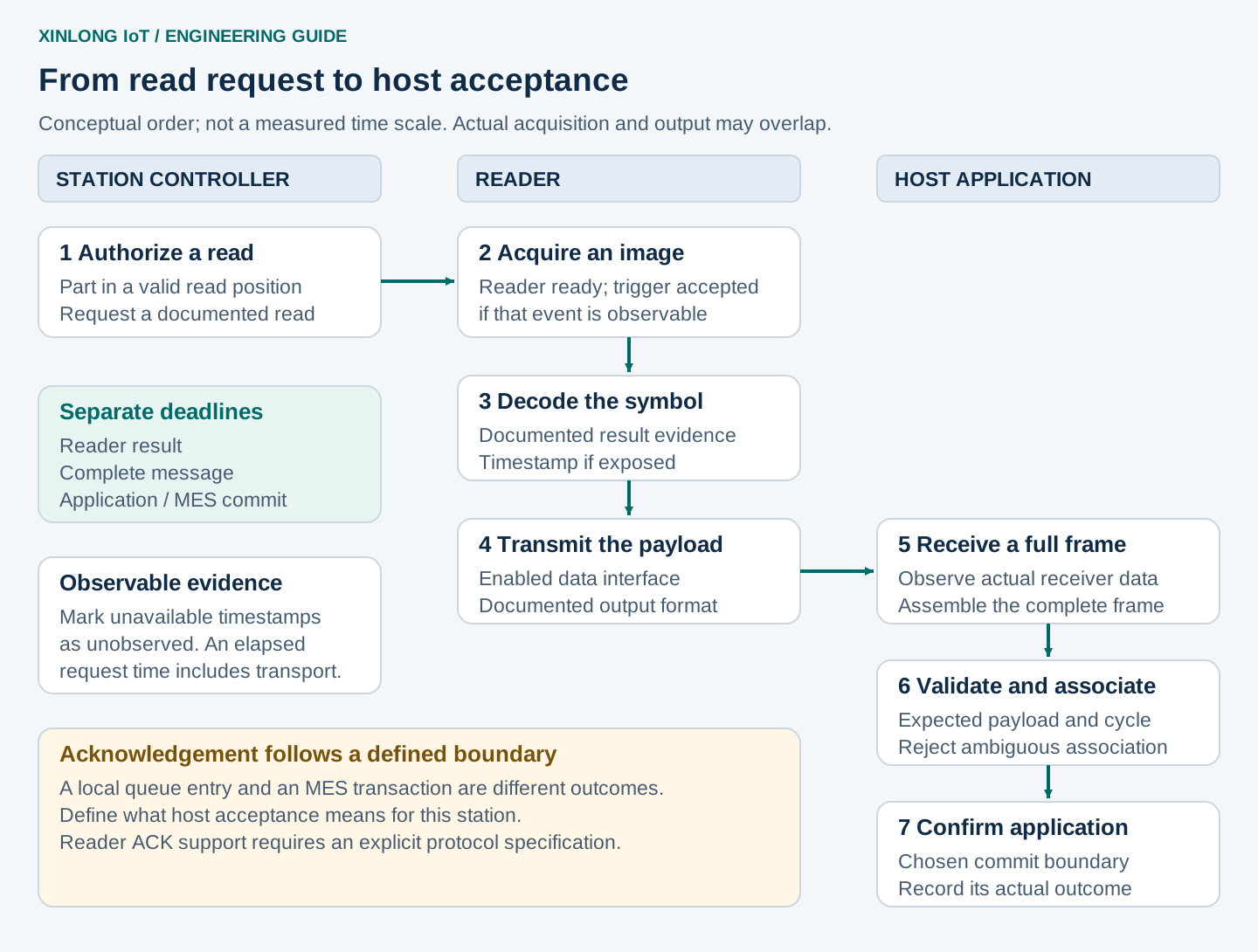
Trace one workpiece through the reader and the host. Record when a read was requested, what the receiver observed and which application record accepted the result. This guide explains that sequence for machine builders and production-station integrators.
The practical rule: give each workpiece a defined read window and a host-owned cycle identifier. Verify the complete received payload before accepting it into that cycle. Keep decode, communication and application failures as separate outcomes.
1. Define what “read successfully” means
A reader indicator and a saved production record describe different stages. Agree which evidence proves each stage on your selected reader, firmware and host interface.
Scroll horizontally to view all columns. Focus the table to use arrow keys.
| Stage | Evidence to capture | Limit of that evidence |
|---|---|---|
| Read requested | Host command sent, or a documented trigger signal applied | A request alone does not prove the reader accepted it |
| Trigger accepted / acquisition started | A documented response or status, where available | Some readers provide no separate observable event |
| Code decoded | Documented decode result or result indication | Does not establish delivery to the application |
| Complete payload received | A complete message at the actual receiver | Bytes or key events may still fail parsing or validation |
| Payload accepted | Expected format and workpiece-cycle checks pass | A local acceptance may still await a database or MES operation |
| Application committed | The chosen application persistence or transaction boundary confirms success | The meaning of “committed” depends on the system design |
Use an explicit unobserved status for stages the equipment cannot expose. A missing observation should not silently become a measured zero-duration stage.
2. Choose the trigger mode around the station
“Fixed-mount” describes the installation. It does not establish which trigger inputs, commands or output protocols a reader supports.
Scroll horizontally to view all columns. Focus the table to use arrow keys.
| Reading approach | Suitable integration pattern | What to verify |
|---|---|---|
| Host-command trigger | A controller requests a read after a fixture or workpiece is ready | Exact command, readiness, response format, stop behaviour and firmware support |
| External electrical trigger | A supported input starts a read cycle | Input voltage, isolation, polarity, pulse requirements and wiring |
| Continuous reading | The reader repeatedly looks for codes while the host manages acceptance | Repeated-output behaviour, object-change logic and how the host gates results |
| Presentation / automatic sensing | A documented sensing mode starts acquisition | What the device senses, its re-arm conditions and how long a code can remain present |
For example, the current G4503 product information lists USB, TTL-232 and RS-232 variants through an 8-pin FPC. It also states that the model has no Ethernet port or opto-isolated I/O. Review its selected version and documented trigger method before designing a PLC connection.
Confirm the electrical meaning of vendor terms such as “TTL-232.” Logic-level UART, RS-232 and a PLC’s industrial input are different electrical interfaces. Connector shape and pin count do not establish compatibility.
For broader selection, use the fixed-mount scanner guide. For a keyboard-versus-serial decision, see USB HID and CDC integration.
3. Separate the optical read window from data deadlines
On a moving line, the code must be captured while it is sufficiently visible and in focus. For a constant-speed, straight-line pass, a first geometric estimate is:
available capture time ≈ usable travel distance / workpiece speed
The usable distance is the section of travel over which the required symbol and quiet zone remain readable under the chosen geometry. It is not automatically the full image width. Evaluate the actual code orientation, motion direction and optical tolerances.
Trigger delay, acquisition scheduling, exposure and jitter use part of that opportunity. The reader may finish decoding and transmitting after the code has left the optical window. A host-commit deadline therefore serves a different purpose from an image-capture deadline.
Define three limits:
- Reader-result deadline: how long the controller waits for a documented result after a request. A no-read response and silence are different outcomes.
- Message-completion deadline: how long the receiver waits for a complete frame once reception begins, using the documented protocol and expected payload limits.
- Application-commit deadline: how long the station waits for its chosen application or MES confirmation before following the agreed hold or recovery procedure.
Measure these at representative payload lengths, workload, lighting and line speed. Do not copy one reader’s decode time into all three settings.
Timestamp host events with a monotonic clock for elapsed-time calculations. If reader and host logs use different clocks, record how they are correlated before subtracting their timestamps. Request-to-complete-frame time includes scheduling and transport; it is not a pure optical decode-time measurement.
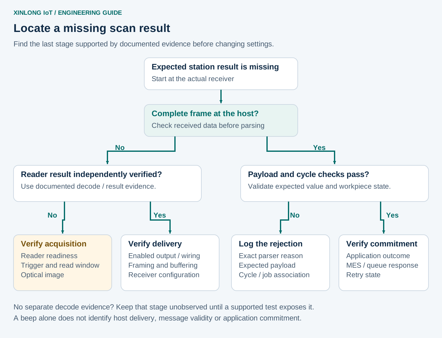
4. Find where the result disappears
Start at the application receiver and work back toward acquisition. Capture data before the parser changes it, using the correct observation method for that interface.
Scroll horizontally to view all columns. Focus the table to use arrow keys.
| Observation | Checks to make next |
|---|---|
| A documented decode indication is present, but the receiver sees nothing | Enabled output interface, selected device/port, wiring, electrical levels, flow control and receiver state |
| Bytes arrive, but no complete frame is produced | Documented framing, length, delimiter handling, receive buffering and completion timeout |
| A complete frame is rejected | Prefix/suffix, encoding, symbology identifier, allowed format, leading zeros and expected payload |
| Correct data reaches the wrong UI field | USB HID keyboard focus, keyboard layout and application input routing |
| Correct data is parsed, but the production record remains pending | Cycle association, application validation, transaction result and MES response |
| No documented decode evidence is available | Reader readiness, accepted trigger method, optical window, image quality and supported result reporting |
A serial receive callback may contain part of a message or several messages. Build frames according to the documented protocol rather than treating every callback as one barcode. TCP also presents a byte stream, where applicable. A live Ethernet connection alone does not define the reader’s application protocol.
For text output, compare an escaped or hexadecimal capture with the intended value. A line ending, leading zero or group separator can affect parsing. Record the interface’s configured output representation; do not assume all readers transmit identical characters for the same symbol.
5. Bind each accepted result to one workpiece cycle
The host should open a cycle from a reliable station event, such as a fixture-ready state or a tracked part entering the reading position. Create a cycle_id before authorizing the read. Keep identifiers unique across restarts, using a run identifier where needed. Retain a separate attempt_id for diagnostic retries.
Within that cycle, define which payload is expected: a specific serial number, an allowed work-order format or a documented code-selection rule. Format checks alone cannot prove that a physically adjacent code belongs to the current part.
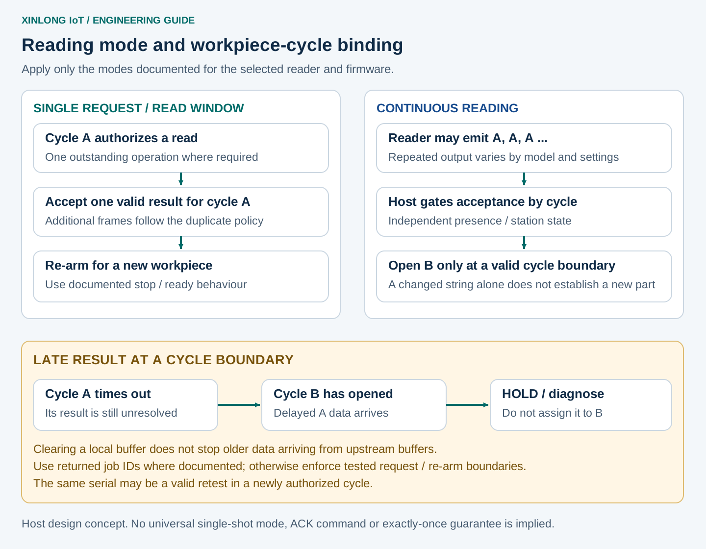
When the protocol returns a job or request identifier, verify its documented meaning and match it to the outstanding operation. When output contains only the barcode string, association needs additional constraints. These may include one outstanding request, documented stop/re-arm behaviour and a controlled workpiece boundary.
Handle late data explicitly. If cycle A times out, an old result can arrive while cycle B is open. Clearing a local receive buffer cannot prevent a reader or transport buffer from delivering older data later. A changed barcode string also cannot establish a new workpiece by itself. Hold ambiguous results and follow the documented reset/re-arm procedure before resuming acceptance.
Define duplicate policy by cycle and business operation. Repeated frames within one cycle should not silently create multiple production transactions. A repeated serial in a newly authorized retest may be valid.
For a retried MES operation, retain the same business idempotency key where the backend supports it, for example station_id + cycle_id + operation. Keep diagnostic attempt numbers separate. This helps the backend recognize a repeated operation; it does not by itself guarantee end-to-end exactly-once processing.
6. Define the acknowledgement boundary
An application acknowledgement should state what has actually succeeded. For one station that may be local validation and a durable queue entry. For another it may be a confirmed MES transaction. Document that boundary so a green station result has one agreed meaning.
A transport acknowledgement or an open connection does not prove that the production record was committed. Likewise, sending ACK to a reader is useful only when its protocol documents the relevant handshake.
Log these outcomes separately:
- Reader no-read, reader timeout or device unavailable, according to the evidence the interface exposes.
- Incomplete frame, invalid payload or ambiguous workpiece association.
- Duplicate output, application rejection or uncertain backend commit.
After an uncertain backend commit, reconcile the existing operation before submitting a replacement transaction. Retry behaviour belongs in the station and backend design.
7. Validate failures as well as successful reads
Use the downloadable trigger and host acceptance test record. It is a blank planning template, with no measured results or preset pass rate.
Exercise these conditions before release:
Scroll horizontally to view all columns. Focus the table to use arrow keys.
| Test condition | Evidence to collect |
|---|---|
| Read request before the station is ready | Whether the request is refused, queued or accepted under the documented behaviour |
| Code near the edge of the usable read window | Part position, trigger timing, acquisition evidence and complete-frame arrival |
| Code remains in view | Repeated-output behaviour and number of accepted business operations |
| Two messages arrive together, or one arrives in fragments | Parser framing result and exact payload preservation |
| Reader result arrives after cycle timeout | Whether the old result is held and prevented from being assigned to the next cycle |
| Host link disconnects during reception | Incomplete-frame handling, reconnect state and re-arm procedure |
| MES response is delayed or lost | Pending state, reconciliation and idempotent retry behaviour where supported |
| The same serial is presented in a valid new retest cycle | Explicit authorization and correct cycle association |
Log the reader and firmware version, interface configuration, cycle identifier, request time, observable result status, first received data, complete frame, validation outcome and commit outcome. Mark unavailable timestamps as unobserved. Keep received payload data according to the project’s handling rules.
For optical and sample boundaries, pair this record with the DPM sample-testing checklist. For PCB-specific cycle handling, see the G53-AI test-fixture integration article.
Frequently asked questions
Why does the scanner beep while the software receives no barcode?
First establish what that beep means in the reader configuration. If decoding is confirmed, inspect the enabled output interface and receiver. Then check message framing and parser rejection. The indicator alone does not locate the failure.
Can continuous reading produce one result per part?
It depends on documented reader behaviour and host cycle control. A reader may repeat a code while it remains visible. Use independent workpiece tracking or station state and an explicit acceptance policy; verify repeats, retests and delayed results.
Does an RS-232 or Ethernet connection mean the reader supports PLC triggering?
The data interface does not establish trigger-command support or discrete I/O. Verify the exact model, electrical interface, protocol and firmware. A gateway or station host may be required.
Plan a sample integration review
Send Xinlong IoT the reader model or installation constraints, a representative code, workpiece motion, host interface and expected output format. Include the trigger approach and the event your application treats as successful acceptance. This gives the evaluation a defined optical target and a defined host result.