G53-AI 6.2g Bare-Board AI OEM Scan Engine for PCB Test Fixtures: 12-Pin FPC Integration & MES Traceability
In an automated PCBA In-Circuit Test (ICT) or Functional Test (FCT) station, capturing a barcode is only the first millisecond of the workflow. The decoded serial number must be bound to the board, the test cycle and the MES record — without cross-board mix-ups or duplicate reads.
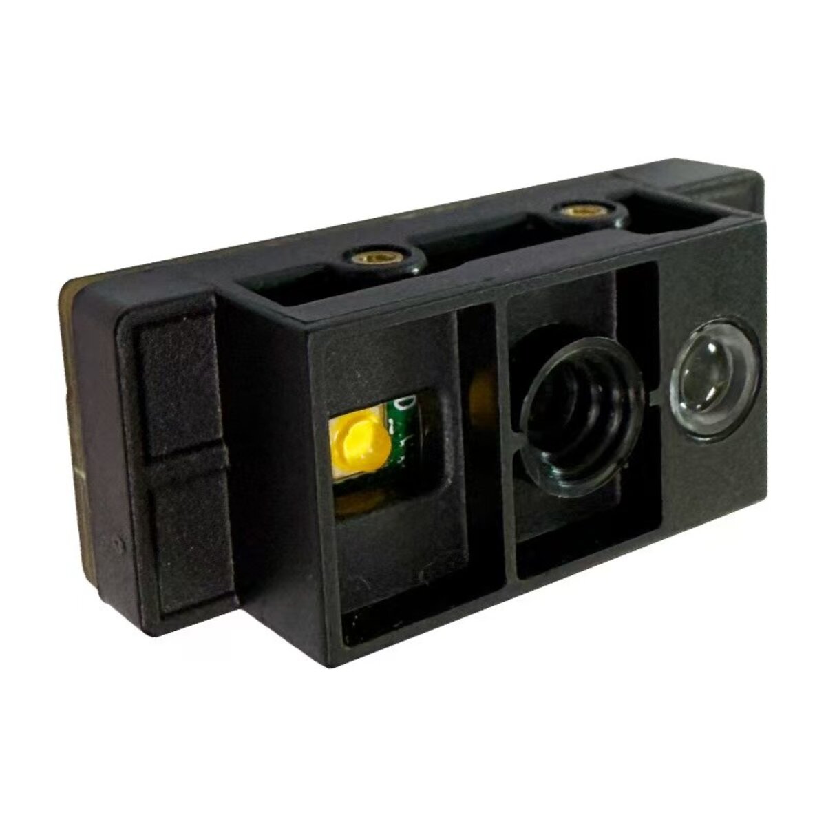
Single-board clamshell jigs with bracket space usually take our enclosed 16.8 mm G4503 fixed-mount DPM scanner. Multi-cavity test heads, ultra-compact probe sub-assemblies and automated medical IVD analyzers need an open-frame optical core instead. This guide covers evaluating the 30 × 15.5 × 13 mm (6.2 g) G53-AI bare-board AI OEM engine over its 3.3 V 12-pin FPC, and binding its output to the test-station state machine.

1. Start with the actual Data Matrix or DPM code on the PCB
A Data Matrix on a board may be printed on a polyimide label or marked directly into the substrate. Direct Part Marking (DPM) describes how a mark is permanently etched or dot-peened into a surface. A high-contrast label, a laser-etched mark on green, black or blue solder mask, and a mark under conformal coating each need different illumination and decoding.
- Prepare multi-lot boundary samples: collect boards across several production batches, including the lowest-contrast laser marks (under 20% PCS), glossy solder mask and curved vial surfaces your quality process accepts.
- Document code geometry and payload: record the expected ASCII format, physical size, cell size in mils (for example 5 mil Data Matrix), board location, orientation and adjacent reflective parts such as copper pads or gold fingers.
- Separate board IDs from panel labels: if the 1280 × 800 field of view captures several codes, define how the host distinguishes the unit serial from carrier-panel or component barcodes. Prefix and length rules filter stray labels; hardware cycle-binding guarantees the serial belongs to the board clamped in the fixture.
2. Review the documented G53-AI bare-board specifications
The G53-AI embeds an AI deep-learning decoding pipeline on the module. Use the documented parameters below — and compare them with an enclosed reader such as the G4503 — to prepare your carrier and electrical evaluation.
| Documented specification | What to verify in your test head or host |
|---|---|
| 1280 × 800 CMOS sensor with global shutter | Image capture under pneumatic clamp motion, rotating carousels and ambient exposure. |
| Warm-white and warm-red LED illumination | Auto/manual red and white settings against your solder-mask colour (green, black, blue) or polished metal and glass, to suppress specular glare. |
| Data Matrix, QR Code and 1D/2D symbologies | Enable only the symbologies your station needs, to maximise decode speed and prevent cross-reads. |
| 30 × 15.5 × 13 mm bare-board body (6.2 g) | Reserve clearance for M-screw mounting, the front optical cone, a 10–15 mm FPC bend radius and service access. |
| 3.3 V DC supply via 12-pin FPC | Design the carrier or EVK wiring strictly around the 3.3 V pinout and peak illumination current. |
| USB VCP, HID-KBW, HID-POS and 3.3 V TTL UART | Confirm the host communication mode, trigger protocol and adapter board for your test PC or PLC/MCU. |
Reference: G53-AI technical specification sheet (PDF).
For baseline reference, bench testing lists working ranges of 75–250 mm on 5 mil Code 39 and 75–230 mm on 10 mil QR Code. Because laser-etched DPM marks vary in cell pitch and solder-mask reflectivity, validate the exact depth-of-field window on your own PCBA inside the available fixture height.
3. Evaluate mounting geometry with the fixture closed
Module thickness (13 mm) and working distance are separate constraints. Clamp the PCBA in its test position, close the pressure plate, and check the optical line of sight with pogo-pin blocks, guide pins and acrylic covers installed.

- Tilt 10°–15° to kill specular reflection: start from a repeatable mount and change one variable at a time (distance, tilt, red/white illumination). Tilting off the perpendicular normal deflects mirror glare from glossy solder mask away from the lens while keeping the code inside the depth of field.
- Archive failed frames: keep raw images from boundary failures so your team can tune exposure parameters.
- Test dynamic cable routing: cycle the lid open and closed to confirm the 12-pin FPC or adapter cable sees zero mechanical strain.
4. Integrate 3.3 V power and the 12-pin interface safely
Because the G53-AI is an open-frame OEM engine in our OEM scan engines range, level matching is mandatory.
- 3.3 V rail — do not apply 5 V directly: never wire a 5 V USB VBUS line to the bare 12-pin connector. Route power through your regulated 3.3 V carrier board or our official USB/RS-232 evaluation adapter. Size the regulator for peak LED current, not idle draw, to avoid sag during trigger bursts.
- USB Virtual COM vs USB-HID for test PCs: VCP lets LabVIEW, Python or C# read strings deterministically in the background without window focus. If you use HID keyboard, verify keyboard language mapping and CR/LF suffixes. See the interface selection guide.
- 3.3 V TTL UART level matching: never connect TTL UART pins directly to an RS-232 port (±12 V) or a 24 V PLC input. Use an RS-232 transceiver or an opto-isolated shifter on your carrier.
- MES/ERP handshake: Ethernet or database transactions are handled by the station host PC or PLC after it receives the decoded payload.
5. Bind each serial number to an active test cycle
For zero-defect traceability in 3C electronics or medical manufacturing, treat capture, validation, electrical test and MES commit as strict state-machine stages.
- Open a cycle: detect clamping, generate a unique
Cycle_ID, purge any previous serial from memory. - Trigger, read and validate: send a hardware or serial trigger, capture the Data Matrix within the timeout, and verify syntax against the active work order.
- Run ICT/FCT: lock the validated serial to the test program, fixture cavity and attempt counter.
- Commit and verify ACK: send serial,
Cycle_ID, PASS/FAIL metrics, timestamp and firmware revision to MES, then wait for the storage ACK. - Release and reset: unclamp and reset the state machine for the next board.
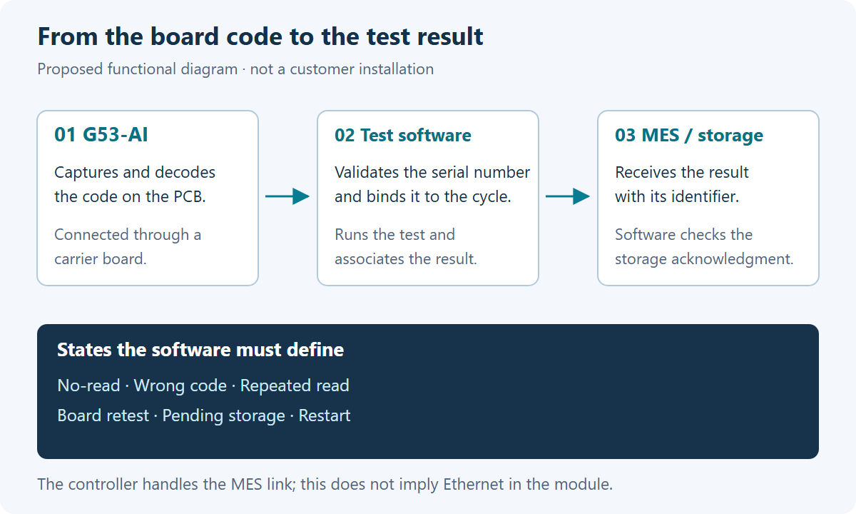
Repeated reads vs legitimate board retests
Two identical strings inside one open Cycle_ID indicate a duplicate trigger read; the same serial after a new clamp event is a legitimate retest. Track both with the Cycle_ID and attempt counter rather than a blind time lockout — or pair the station with our free
barcode comparison and error-proofing software for automatic duplicate interception.
No-read, wrong-code and MES connection loss
Define isolated fault states for a decode timeout (NO_READ), a valid code from the wrong sub-assembly (WRONG_CODE) and an MES network timeout (PENDING_STORAGE). Never populate a failed read with the previous board’s cached serial.
6. Pre-production sample validation matrix
Before freezing the fixture BOM, benchmark the G53-AI sample across 100+ cycles per condition using the log below (see also our G4503 test-jig integration guide for the enclosed-scanner route).
| Validation condition | Metrics to verify and archive |
|---|---|
| Multi-lot PCBs and solder-mask finishes | Expected vs received ASCII payload, Data Matrix mil size, solder-mask glare, illumination setting, first-pass read rate. |
| Mechanical placement tolerances | Working distance, 10°–15° tilt, X/Y displacement across clamp tolerances in the closed position. |
| Missing, damaged or wrong-board code | Immediate fault state with zero carryover of the previous serial. |
| Duplicate trigger vs board retest | Exactly one MES record per attempt, with full retest history preserved. |
| Cable disconnect and power restart | Automatic VCP/UART port recovery and safe handling of uncommitted records. |
| Takt-time breakdown | Separate millisecond logs for decode, electrical test and MES acknowledgment. |
Request a G53-AI sample, 3D STEP CAD and confidential evaluation
To evaluate the G53-AI for a PCB test fixture, multi-up test head or medical IVD instrument, share these parameters:
- Target code: Data Matrix or QR photos, mil size, location on the PCB or vial.
- Mechanical envelope: available working distance and mounting clearance inside the test head.
- Electrical host: preferred interface (3.3 V TTL UART, USB VCP or HID) and carrier requirements.
- Confidentiality: we sign a mutual NDA before reviewing 3D fixture drawings, and supply STEP CAD plus 12-pin EVK adapter boards for bench testing.
→ View the G53-AI product page and request a sample
Related products

Related articles
Evaluating a bare-board engine for an ICT/FCT station?
Send your fixture drawing, PCB code sample and host interface — free sample validation before tooling.
📞 Contact Xinlong IoT