A direct part marking reader should be evaluated on the parts, positions and timing that the finished station will encounter. A clear decode on one carefully positioned sample provides limited evidence for a production decision. Record how the reader behaves when the part, surface and installation vary.
This DPM reader sample testing checklist focuses on laser-marked codes, including PCB applications. It also provides a recording method for other direct marks when the selected reader supports them. Use it to compare a fixed-mount barcode scanner with an OEM scan engine installed in a fixture. Each format still needs its own mounting, electrical and optical checks.
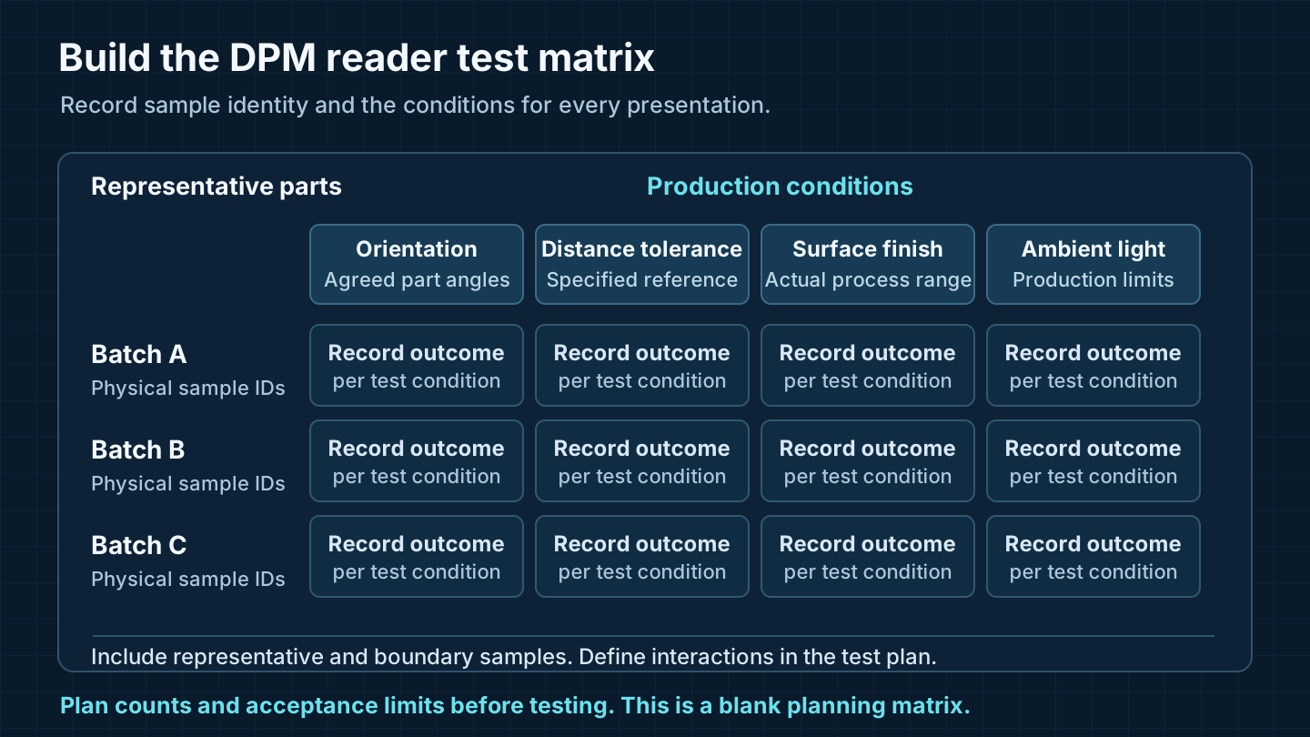
1. Define the parts and expected barcode data
Assign a sample ID to each physical part. Record its marking process, material and surface finish. A printed label attached to a PCB requires different optical evaluation from a code marked directly into the board or its coating. Record the actual target rather than relying on the word “PCB”.
For each code, keep the symbology, overall dimensions and smallest element size separately. For a Data Matrix, the element size is the size of one cell. Include the required surrounding clear area, nearby text and other visible codes. Retain a reference image and an independently established expected payload.
Use parts from relevant production batches and known process limits. Include examples with acceptable low contrast or changing surface appearance. Deliberately rejected marks may be useful diagnostic samples, but identify them separately from the parts the station is required to read.
For the broader relationship between marking methods, optics and decoding, see the direct part marking and DPM barcode reading guide.
2. Record the reader, light and mounting configuration
Before comparing results, save the reader model, hardware revision, firmware and configuration. Include the lens or focus setting, enabled symbologies, exposure mode, illumination, trigger mode and output format where those settings are available. A later change to one of these items creates a new configuration to validate.
Specify the distance reference used in the drawing and test report. Window-to-part distance and distance from an optical reference plane can differ. Record the permitted distance range and lateral or angular movement of the part. Check that the complete symbol and its required clear area remain in view.
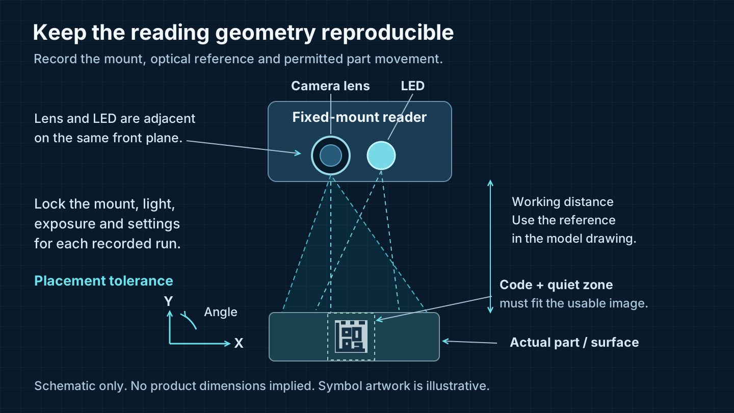
A comparison can have two stages. First, hold the relevant conditions constant to investigate a single change, such as illumination colour. Then tune each candidate within the installation's actual limits and compare the resulting production configurations. Record which stage each result belongs to.
Xinlong's custom F31-BW blue LED PCB demonstration is a relevant lighting example. Its result concerns the demonstrated sample and custom setup. Validate colour, angle and exposure on your own marked surface before applying that choice elsewhere.
3. Build a matrix around production variation
Start with the nominal position, then test the limits the approved fixture and process allow. Choose the sample count and combinations with the responsible engineering and quality teams. One universal count or pass percentage cannot cover every production risk.
Scroll horizontally to view all columns. Focus the table to use arrow keys.
| Test group | Vary or confirm | Keep with the result |
|---|---|---|
| Parts | Approved batches, mark contrast, surface finish, code position and permitted contamination | Sample ID, batch, photograph and expected payload |
| Placement | Near, nominal and far positions; lateral displacement; allowed rotation or tilt | Distance datum, fixture revision and actual position |
| Optical path | Final protective window, mounting bracket, nearby reflective surfaces and obstructions | Window specification and assembled setup image |
| Light | Intended illumination and the ambient-light conditions allowed at the station | Light arrangement, exposure setting and image when available |
| Motion and trigger | Actual part motion, reading opportunity, trigger method and timeout | Speed or motion profile, trigger ID and timing method |
| Host integration | Complete data reception, part association, repeated triggers and recovery | Interface configuration, host log and failure category |
For a moving target, include speed and the interval during which the code can be read. A global-shutter sensor still needs sufficient light, suitable exposure and enough image detail. For a static PCB fixture, check the actual settle condition before the trigger. A stationary desk result cannot establish a moving-line capability.
4. Count physical presentations and keep retries visible
Define one test cycle as one intended physical part presentation, with a known expected payload and an agreed reading opportunity. Identify each presentation separately. If the reader remains in continuous mode, multiple outputs from the same presentation must not increase the number of tested parts.
Agree what the first attempt means for the chosen trigger mode, including its trigger and permitted reading window. A decoder may process several frames inside that window; those frames do not automatically count as retries. A new commanded attempt or extended window must follow the test plan's retry rule. For each presentation, preserve the first outcome, timing and additional attempts.
Scroll horizontally to view all columns. Focus the table to use arrow keys.
| Check | Record | Useful distinction |
|---|---|---|
| Reader data | Matches expected payload, no read, unexpected payload or unavailable reader-level result | An adjacent valid code or output transformation can cause unexpected data. Preserve evidence before assigning a cause. |
| Timing | Within deadline, late, or unmeasured | Record start and end points on a common timebase, or state clock synchronisation and measurement uncertainty. A host timestamp measures that host path, not an isolated decoder time. |
| Host association | Correct part/transaction, missing data, duplicate or misassociation | A beep or good-read indicator alone does not establish the final host record. |
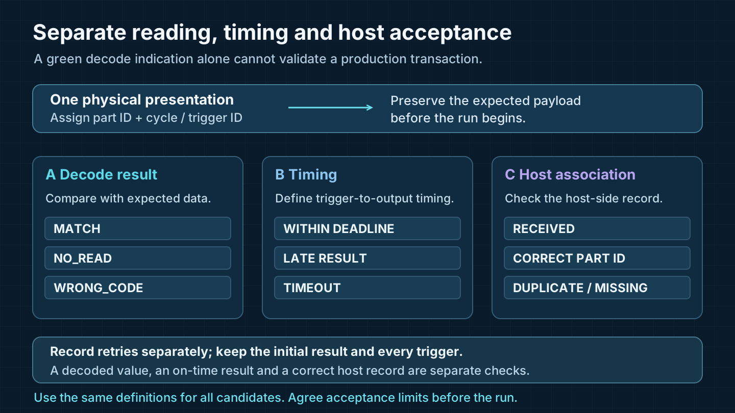
For an agreed set of N eligible presentations, an end-to-end first-pass acceptance rate can be defined as:
100 × presentations with correct data on the first attempt,
      received within the agreed deadline and bound to the correct part
    / N eligible presentations
Define eligibility and exclusions before the run, and report the excluded count with its reason. Keep separate counts for unexpected data, no reads, late results, duplicates and retries. If reader-level data is unavailable, label the measurement as host-observed acceptance. Do not infer an optical failure from a missing host message alone.
The USB HID and CDC integration guide explains why decoder output, host reception and application acceptance need separate checks.
5. Download a blank test record and agree acceptance
The CSV below contains two blank record rows and a separate units row. Use one record per presentation and attempt, so retries remain traceable. Enter the expected and received payload according to an agreed encoding; preserve leading zeros. For binary or control characters, keep an unambiguous hexadecimal record.
Download the blank DPM test record (CSV)
Set payload columns to text when importing the CSV into a spreadsheet. Operational barcode data can contain spreadsheet formula characters; import it as text and handle confidential identifiers inside your own approved system. The template contains no customer data or performance results.
The record covers sample and configuration IDs, material and marking process, symbology, element and code dimensions, position, light, motion, trigger, payload, result and timing. Define the allowed failure categories, latency measurement and production acceptance limits in the test plan. Keep the configuration and evidence with the report so another unit can be checked under the same conditions.
A reader test measures the selected system's ability to read the tested parts. Formal direct-mark symbol quality verification, where applicable under ISO/IEC 29158, needs a suitable calibrated verifier and specified measurement conditions. Successful decoding by a scanner does not establish a formal symbol grade.
6. Choose the integration path for the validated setup
Use the test report to select a reader format and identify remaining integration work:
- For an enclosed station reader, start with the fixed-mount DPM reader selection and evaluation page. Confirm the particular model and configuration on the submitted parts.
- For a compact fixture or a device built around a bare-board module, review OEM barcode scan engines. Include the final window, supply, interface and released mechanical drawing in the validation.
- For broader label, QR or mixed production tasks, compare the fixed-mount 2D barcode scanner options. A category label alone cannot establish DPM performance.
For screen codes and kiosk windows, use the separate embedded QR module sample validation checklist. It covers a different target and should be applied with the appropriate samples.
Practical questions before sending samples
How many parts should a DPM reader sample test include?
Agree the count with engineering and quality based on process variation and the cost of a missed or incorrect result. Identify the batches, boundary conditions and repeated presentations being covered. A small successful demonstration establishes only the tested conditions.
Can a fixed-mount QR code scanner read laser-marked Data Matrix?
QR and Data Matrix are different symbologies. Confirm the selected reader supports the actual symbol, then test the marking process, cell size, contrast and geometry. Support for printed 2D codes alone does not establish direct-mark reading performance.
What should I send for an initial evaluation?
Provide representative parts or clear images, expected payloads, code and cell dimensions, material, marking method, permitted positions and cycle timing. Include the proposed reader format and host interface. Confirm how confidential parts and identifiers should be handled before sharing them.
Plan a DPM sample evaluation
Share the real code, material, mounting range and host requirements. Xinlong can use those inputs to shortlist a configuration and define the tests needed for your project.