Selecting an OEM barcode reader starts with the code, the available optical path and the data your host must receive. A reader that works on a desk may behave differently behind a kiosk window, next to PCB fixture probes or when connected to an access controller.
This OEM barcode scanner selection guide covers PCB test fixtures, QR/NFC access terminals and self-service kiosks. Use the engineering checks below to shortlist a reader format, confirm the ordered interface version and plan sample testing before freezing the enclosure and bill of materials.
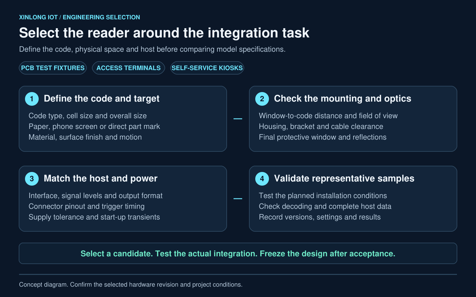
1. Define the code, target and host requirements
Record the conditions the finished device must handle. For a small code, distinguish its overall dimensions from the size of one bar or matrix cell. For a screen code, include display brightness and screen reflections. For a directly marked part, retain samples from the actual material and marking process.
Scroll horizontally to view all columns. Focus the table to use arrow keys.
| Requirement | What to record |
|---|---|
| Code and data | Symbology, smallest element size, overall dimensions, surrounding clear area and expected decoded string |
| Target | Paper, phone screen, label or direct part mark; surface finish, curvature and production variation |
| Installation | Window-to-code distance range, viewing angle, available field of view, protective window and obstructions |
| Motion and timing | Static or moving target, speed, trigger source, reading opportunity and required response |
| Host and power | Interface, signal levels, output format, supply version, cable and start-up requirements |
| Acceptance | Agreed definitions of correct reads, missed reads, unwanted reads, latency and operating stability |
Use these inputs to choose between an enclosed fixed-mount reader, a bare-board scan engine or a panel-mounted module. The OEM scan engine selection page and fixed-mount reader comparison provide candidate models; the product page and released drawing define the version to evaluate.
2. Check mounting clearance and the optical path
A thin housing helps a PCB fixture fit around probes and pressure plates. The design must also provide the working distance required by the actual code, an unobstructed field of view and room for cables and brackets.
The G4503 fixed-mount reader has a published housing thickness of 16.8 mm and a listed 30–300 mm working range. Establish the usable window for your code and surface by testing. A general range in a product listing cannot establish the near limit for every laser-marked PCB.
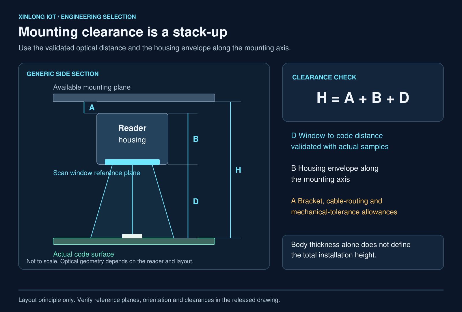
For a simple axial layout, budget the housing dimension along the mounting axis, the sample-validated window-to-code distance and the required installation allowances. If a particular layout has a confirmed 16.8 mm axial body allowance and uses a validated 50 mm reading distance, its base envelope is 66.8 mm before brackets, cable routing and tolerances. This example does not establish a universal minimum clearance or a rule against direct mounting below 60 mm.
Download the G4503 3D CAD STEP file to check the enclosure and mounting geometry, and use the PCB test-jig integration article for further layout considerations. Verify the optical reference plane and selected lens configuration with the sample unit.
When the validated optical path cannot fit above the board, request a mechanical and optical review of side mounting or a folded path. A mirror layout needs checks for total optical length, clear aperture, image orientation, illumination, glare and decode stability. Approve it after prototype tests on representative marks.
3. Match the host interface, connector and output format
Check the communication interface separately from the connector. Pin count and pitch describe a physical connection; they do not define supply voltage, logic levels or the data protocol. TTL-level UART and RS232 use different electrical levels.
For the G53-AI bare-board scan engine, confirm the released 12-pin FPC pinout and the ordered USB or TTL UART configuration. Compare the contact side, pin assignments, supply and signal levels, mounting datums, trigger timing and command set before connecting a host. Check the exact hardware revision when evaluating a replacement for an existing engine.
The G53-AI PCB fixture guide explains its bare-board integration role. A matching connector alone cannot establish electrical or firmware compatibility with another manufacturer's engine.
Wiegand QR code reader integration
For a turnstile or door controller, agree how barcode and NFC data become credentials. Standard Wiegand 26-bit and 34-bit formats have limited payload capacity and cannot transparently carry arbitrary-length QR text.
Confirm parity, field layout, byte order, QR-to-credential mapping and duplicate handling with the controller supplier. Blind truncation can map different credentials to the same value. Select a supported serial or network interface when the application needs the original full payload.
An Ethernet connection also requires an application-level agreement: message framing, destination, acknowledgement, timeout and retry behaviour must match the receiving system. The XL-D52-E access reader lists Ethernet and HTTP/HTTPS/TCP/UDP options; confirm the interface and firmware configuration supplied for your project.
4. Compare reader formats for the application
PCB test fixtures and production stations
Compare enclosed readers with bare-board modules against the available mounting envelope and maintenance needs. The G4503 is an enclosed fixed-mount candidate. The G53-AI provides a bare-board global-shutter option for compact equipment. Global shutter describes exposure architecture; acceptable motion performance still depends on exposure, light, image sampling and the target speed.
The DPM reader selection page lists candidates for direct-marking projects. Validate laser-etched and dot-peened codes separately on the selected model. Cell size, mark depth, surface finish and illumination can change the result; membership of one product category does not establish equivalent DPM performance.
Access control panels and turnstiles
Start with the QR/NFC access reader selection, then compare the reader's mounting format and supported output with the access controller. F21-NFC-W is a candidate for embedded QR/NFC integration; request the current released drawing and wiring information for the exact version before fixing the panel cutout or controller connection.
The XL-D52-E provides an 86-box format for access applications. Test the actual badges, NFC credential type, printed passes and phone screens, then verify that the controller receives the expected credential once per intended presentation. Reading a card UID does not by itself define credential authentication or door-authorisation logic.
Self-service kiosks and compact terminals
The F4100 kiosk barcode module lists 4000 K warm-white illumination and USB, TTL UART and RS232 options. Its 10-pin SH-1.0 connector includes a TRIG line for host-controlled capture. Confirm the output and trigger configuration for the ordered version.
The XL-F3-BW OEM scan engine is another candidate for a space-constrained device. Its published specification gives a 3.3 V supply and approximately 200 mW typical power. Size the host supply from verified start-up and illumination transients, voltage tolerance and the selected interface arrangement.
For a barcode scanner behind protective glass, test through the final window material, thickness, coating and mounting position. Repeat screen-code tests at the intended brightness range. Window reflections and enclosure edges can affect a result that looked acceptable with an exposed module.
For a counter where embedding is unnecessary, compare desktop scanning platforms. The XL-P80 offers a physical 2D-disable control that can help reduce unwanted 2D reads during 1D-only operation. Confirm the selected mode, supported symbologies and setting retention in the workflow.
Shortlist and integration checks
Scroll horizontally to view all columns. Focus the table to use arrow keys.
| Candidate | Format and main check | Host connection to confirm |
|---|---|---|
| G4503 | Enclosed fixed-mount reader; validate the PCB mark and mounting envelope | USB / TTL-level serial / RS232, according to ordered version |
| G53-AI | Bare-board global-shutter engine; check mounting, supply and exposure | USB or TTL UART configuration; released 12-pin FPC pinout |
| F21-NFC-W | Embedded QR/NFC candidate; confirm released mechanical and wiring drawings | Match the exact output version to the controller |
| XL-D52-E | 86-box QR/NFC access reader; check credential and network handling | Ethernet / Wiegand / USB / serial options; firmware protocol configuration |
| F4100 | Kiosk module; test screen codes through the assembled window | USB / TTL UART / RS232; 10-pin SH-1.0 with TRIG |
| XL-F3-BW | Compact OEM engine; check 3.3 V supply and transient demand | USB / TTL-level serial; confirm any required RS232 adaptation |
| XL-P80 | Desktop platform; confirm wanted and unwanted symbologies | USB-HID / USB-COM / RS232, according to ordered version |
5. Validate samples before the design freeze
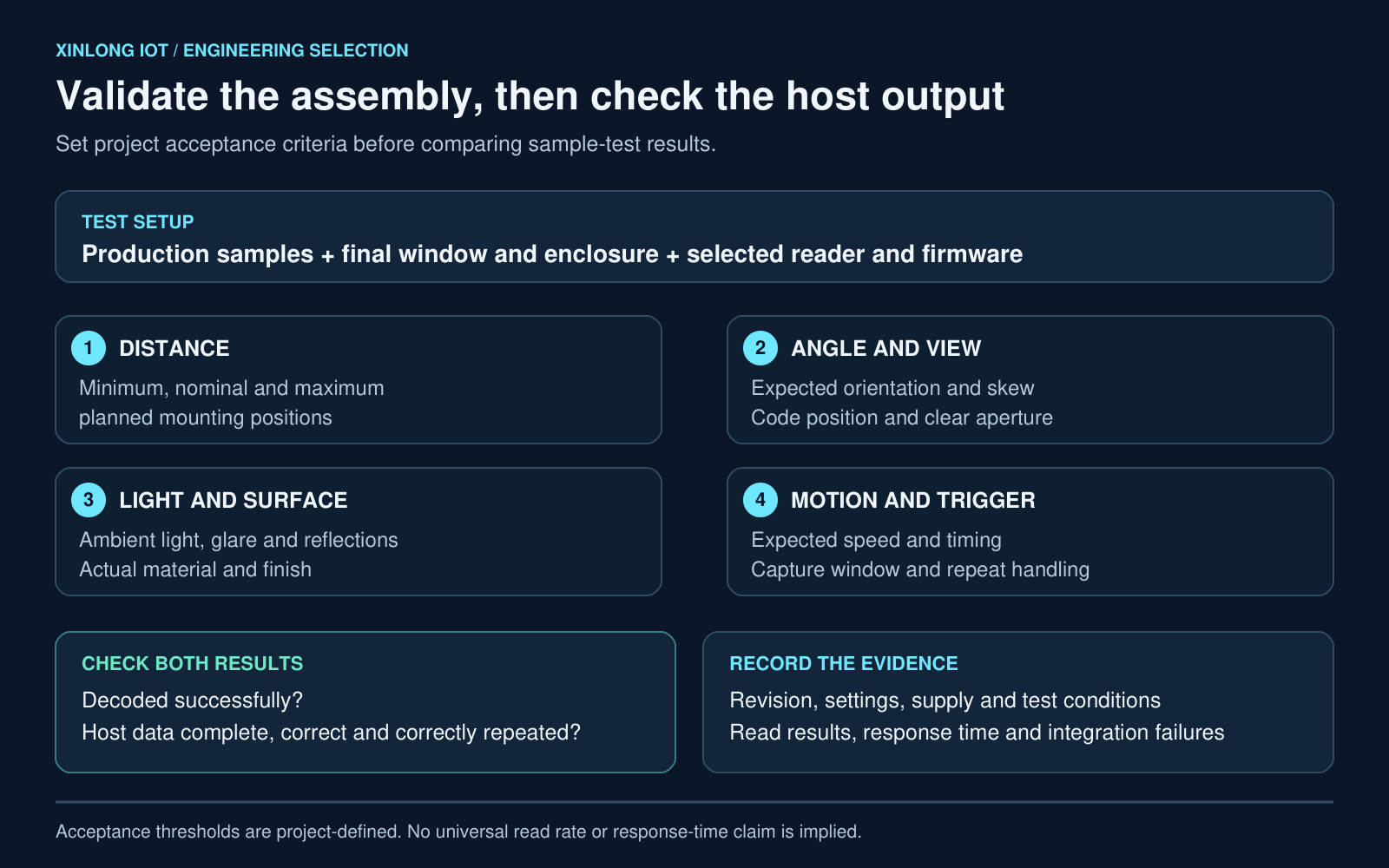
Use production-representative codes in the final window and enclosure arrangement. Include the smallest elements, weak marks, reflections and expected batch variation. A successful desk demonstration establishes a starting point for these tests.
Scroll horizontally to view all columns. Focus the table to use arrow keys.
| Test group | Conditions to cover | Evidence to keep |
|---|---|---|
| Samples | Code types, smallest elements, low contrast and production variation | Sample IDs, photographs and expected strings |
| Mechanics and optics | Minimum, nominal and maximum planned distance; angle; window; obstructions | Drawing revision, reference planes and captured images |
| Light and motion | Intended ambient conditions, reflections, movement and trigger opportunity | Exposure or operating settings, speed and lighting arrangement |
| Host and supply | Interface, logic levels, output format, start-up, repeated triggers and reconnects | Firmware version, wiring revision, supply measurements and host logs |
| Results | Correct reads, missed reads, wrong data, duplicate output and response time | Attempts, failures, measurement method and agreed pass criteria |
Count a result as correct when the host receives the complete expected string in the intended transaction. Check trigger-to-output association and duplicate handling. Record the module version, firmware, interface settings and supply so a later unit can be tested under the same conditions.
Use the embedded QR module sample validation checklist for further guidance on phone screens, protective windows, communication and power stability. Keep failed samples and the settings used for them; they help define the limits of the approved configuration.
Download an OEM scan engine integration test record
Use this blank OEM scan engine integration test record (CSV) to connect a sample result to its mechanical drawing, firmware, interface variant and host settings. It includes checks for the final protective window, power at the module and the exact string received by the host. Copy the test-run rows for each sample group or installation condition.
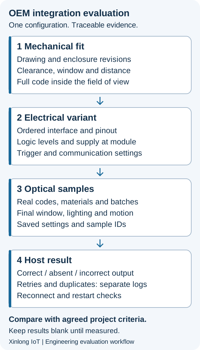
Before an OEM scan engine sample evaluation, define one presentation, the expected host string and the initial response deadline. Classify the first response to each presentation as correct, no output by the deadline, or incorrect output. An incorrect host string does not by itself identify a decoder fault; retain the raw module output and host capture to locate the difference.
Record extra outputs separately, including duplicate output within the same intended transaction. Keep retry attempts and their results outside the first-pass count. A result accepted after a retry may satisfy the business workflow while still failing the agreed first-pass target. The CSV leaves observed values, results, evidence and owners blank for your project team to complete.
6. Request an OEM sample review
Share the code type and size, mounting-distance range, target material, host interface and power supply. Include representative code images, expected data and an enclosure drawing if available. For a replacement engine, add the exact existing part number, revision and approved interface documentation.
Xinlong can use this information to shortlist a reader and identify the sample tests needed for your device. Confirm the released specification, wiring and sample results before freezing the enclosure or ordering production quantities.